Don’t get stressed out when you simulate your PCB with digitalization – part 7 of 8
Automakers will need to take a closer look at the electronic component analysis processes of the next generation of electronic circuit boards to ensure the vehicle will be able to accomplish this.
As crucial as validating the safety and functionality of vehicles is now, it will be even more crucial as autonomous and electric vehicles hit the road. Customers want to feel confident that their vehicle will safely get them from one destination to the next – especially when they aren’t in the driver’s seat.
Conducting electronic stress analysis is not a new concept, but until recently, it has not been practical. In any electronic system that’s functioning and heating up, temperature changes and vibration introduce stresses. Let’s take each one separately.
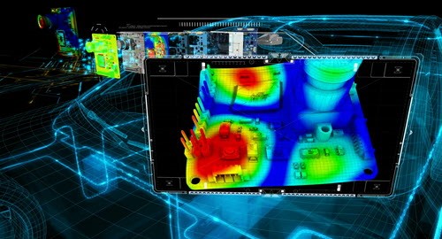
Thermal stress. Temperature changes and the difference in thermal growth of materials trigger thermal, structural stress. When a microcontroller starts to run, it initially heats up locally, causing the chip to expand. The circuit board, however, is not heating up as fast, and does not expand at the same rate. This is further complicated by the fact that the chip and board have different rates of growth in response to the temperature.
The net effect is that the controller solder joints become strained due to this growth difference.
As this cycle repeats, cracks can initiate and ultimately propagate through the joint, resulting in a break in the electronic circuit: failure. In many cases, this is the main failure mechanism of such a system.
If you consider the number of solder joints connecting resistors, capacitors, controllers and transistors in such a system, and that a failure in any one of them can result in operation malfunction, it’s no surprise that safety-critical systems need to be stringent to address these issues.
Vibration stress. Vibration stress is often neglected from the simulation process, and one of the major challenges is new random vibration requirements.
Previously, vibration testing was done using harmonic sine sweep processes. The electronic module was placed on a vibration shaker table and shaken at one sinusoidal frequency, and over time, this frequency was changed to higher or lower levels. Evaluating this in CAE simulation is fairly straightforward.
However, the industries understood that real-life vibration is represented by multiple frequencies acting in a more random pattern. While testing protocols have been developed to reproduce such scenarios, vibration stress simulation that can be used in fatigue assessment still lags. But the industry is making headway and improvements in electronic component analysis as well as thermal stress analysis. New simulation technologies to evaluate stress response to random vibration, and related cycle counting techniques for fatigue and durability assessment are now available in simulation codes.
Traditionally, circuit boards were overdesigned resulting in higher costs, mass and production time or designed to be expendable to compensate for what could not be simulated in real life. However, this is no longer an option.
Companies need to achieve optimal performance at the lowest possible costs, and digitalization can help get them there.
Ultimately, thermal, vibration and electrical stress simulations and analysis should be performed together, as this represents real life.
This concludes the seventh part of our series on electronics systems and the challenges to provide solutions for products of the future. If you wish to start from part 1, please click here.
About the author
Greg Roth is the director of automotive and transportation solutions in the Industries Group at Siemens PLM Software. In his current role, he champions CAD, CAE & PLM technologies and processes for companies at a global enterprise level so they can achieve substantial reductions in product development costs and time while improving overall quality. He previously held positions at Ford Motor Company, Eaton Corporation and Amcor Packaging. He was also chief engineer for the CAE and NVH departments at ZF-TRW Automotive North America Braking Systems in Livonia, Michigan. Greg holds an master’s degree in mechanical engineering from the University of Michigan, a master’s degree in electronics and computer controls engineering from Wayne State University and a bachelor’s degree in mechanical engineering from Michigan State University.