Tips and Tricks from Forum Users #21

Here’s a collection of the most interesting tips and tricks derived from the discussions on the Solid Edge forum.
Due credit is given to respective contributors.
And a quick list of the previous compilations:
T&T #01, T&T #02, T&T #03, T&T #04, T&T #05
T&T #06, T&T #07, T&T #08, T&T #09, T&T #10
T&T #11, T&T #12, T&T #13, T&T #14, T&T #15
T&T #16, T&T #17, T&T #18, T&T #19, T&T #20
1. How do I set up some custom textures that are frequently used by our design team, ideally a common folder?
The Tip: You can place the textures on a network drive, where everybody has access to. These can then be used in styles and it saves them in the material.mtl.


Contributor: @Sander-NL
2. How do I get rid of the side jog on a Y-axis dimension which looks like this:
The Tip: Grab the handle at the end of the Break line near the text and drag back to the dim line.
 Contributor: @KennyG
Setting the break line value (lines and coordinate tab) to 0.0 seems to do it.

Contributor: @bshand
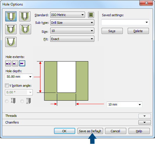
3. The default hole extent is set to ‘Through All’, but for my projects ‘Through Next’ is preferred. I have changed the extent many times while creating holes, hoping that it will default to the last used option but it doesn’t. Where can I change the hole default extent?
The Tip: Set your options to what you want them to be, then click the ‘Save as Default’ button before clicking ok on the dialogue, that should do it for you.  Contributor: @nominus38
4. How can I pattern/copy a part within an assembly without creating a pattern? I need to pattern a part multiple times with a fixed distance between each along the x-axis. In my old CAD program, I just select the part, define the axis and then type how many copies I want with the distance between each. Something similar in Solid Edge?
The Tip: Sure, Just use a Pattern Along Curve. Select the parts, start the pattern feature, an edge (axis), number and distance. The result should be what You expect it to be. Watch this video for the steps:
Contributor: @hawcad
Video by: @Tushar
5. I need to place a cutting edge (for a section view), 25 mm. from the end of my part, but Solid Edge changes the dimensions to 50% of the correct value. See video:
The Tip: If you need an exacting location for section lines, I normally just use relationships when drawing the cutting plane profile, but have also used sketch geometry placed within “Draw In View”, then locating the cutting plane profile to match that sketch, with relationships as needed.
Contributor: @SeanCresswell


Comments