The 10 Golden Rules of Solid Modeling

Even as synchronous modeling makes great strides with each new release of Solid Edge, I thought of taking a hint from Matt Lombard‘s following quote in his very useful guidelines for blog authors.
You may think it’s a boring topic because you deal with it every day, but someone will find it interesting.
The following are best practices that will help the novice user and 3D expert alike, generate robust solid models. These 10 commandments can save hours of work each day by saving design time and allowing changes to be absorbed easily.
1. Make the Base Feature Symmetric
This is a no brainer but here are some Do’s and Don’ts:
• Don’t use dimensions to make a rectangle symmetric about the planes.

• Use the Horizontal/Vertical relation to make the rectangle or base feature symmetric about the default reference planes.

Though dimensions appear to be a more attractive option, easy to place and interpret compared to relationship handles, it unnecessarily adds more clutter and more numbers to keep a tab on during later design changes.
2. Use Relationships
Constrain your sketches as much as possible, before applying any dimensions.
Always keep the dimensions for later.
Also don’t use mathematical relations between dimensions for such simple tasks as making the sketch symmetric but save those techniques for capturing the design intent.
Many users do not use relationships beyond those applied automatically by Solid Edge.
Relations applied initially can be lost easily during profile editing operations like trimming, etc. Applying relationships explicitly is a highly recommended practice.
3. Also, rename dimensions to something more meaningful and use the comments.
It really helps the next guy when changes are necessary.
After placing the dimension, double-click it to bring up the Command bar which sports the areas for renaming and adding comments.
The makers of Solid Edge sure have spent much time and energy in adding these facilities – go ahead and make the most of it.
If nothing else, it can be used to take down a little reminder when you get that all important phone call in the middle of placing a critical dimension ![]() Rest assured you will never lose the comment for it will always be found under the Comments column in the Variable Table as illustrated in image above.
Rest assured you will never lose the comment for it will always be found under the Comments column in the Variable Table as illustrated in image above.
4. Reuse is the Mantra
In Solid Edge, dimensions placed in the sketcher mode appear AS-IS in the final drawing.
This leads us to adopt another best practice which is placing key dimensions in the sketcher itself so they appear in draft automatically using the Retrieve Dimensions  tool.
tool.
Retrieved dimensions seen on the drawing make their way all up to the shop floor and when there is a feedback on tweaking one of them, you can come back and find the dimension readily in the model applied inside the sketcher. This:
• Saves time spent on adding a dimension in the sketcher.
• Avoids the risk of losing the design intent.
• Breaking the already placed relations.
• Over-defining the sketch.
5. Do not apply too many fillets or chamfers in the sketch.
Always apply treatment features to the solid model. With too many entities in the sketcher, the model takes more time to regenerate, since it has to resolve more constraints and geometric relationships that Solid Edge applies for you in addition to the dimensions placed manually.
Take for example a fillet used in a sketcher. Here you have to apply a radius dimension explicitly. On the other hand, using the Round tool you have a dimension placed automatically.
6. Create Drafts as Early as Possible
Some features, by their nature, should be applied early in the modeling process.
Draft features are such an example.
A draft feature allows you, the designer, to draft or taper a face or group of faces, so that the model can be extracted from a mold. Once an edge has been rounded, a surface that borders it cannot have a draft applied. This makes it important to apply drafts before fillets.
Draft features rely on sharp corners to use as hinges for the surface to be drafted. For that reason, it is advisable to create drafts as early as possible, in order to avoid difficulties when creating draft walls.
7. Chronology of Fillets
Create Fillets as late as possible.
Just as drafts should be created as early in the model, fillets should be created later.
Filleting the edge of a face prevents that face from being drafted later. The extra edges created by fillets becomes selectable as reference for later features, and can therefore cause parent-child relationships that are undesirable.
Few models will have all the fillets as the last features, but creating them as late as feasible in your design allows more design freedom.
8. Chronology of Fillet Radius
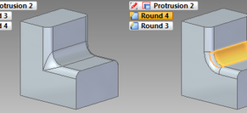
Apply larger rounds first.
Suppose you apply the small round first. And then the larger round.
Not only, Solid Edge senses it as a feature with problems, but the result is also not the desired one.
You can rectify this problem by dragging and dropping the last round feature before the previous one in the feature pathfinder. This is also called feature re-ordering.
And even though, feature reordering is a handy tool, apply larger rounds first.
9. Parent-Child Relationships
Be aware (not beware!) of parent-child relationships.
Parent-child relationships help capture design intent, but can also be a source of frustration if used haphazardly.
Dimensioning a hole to the edge of a protrusion, makes the hole a child of that referenced feature. In this case, if the protrusion is deleted, then the hole no longer has it’s parent, and the child becomes a failed feature.
In this case, it is recommended to dimension the hole to the edges of the face on which it is created.
It is best to dimension to a reference plane or axis. Dimensioning to a face or edge WILL cause problems if that face changes.
Here is a list of some methods that create parent-child relationships :
• Dimensioning to existing geometry.
• Coincident, collinear, tangent, parallel and perpendicular constraints between profile geometry being created and existing model geometry Included in the sketcher.
• Reference plane location reference. Any surface used to locate a new reference plane and then features created on the new reference plane.
• Mirroring a feature.
• Grand Children – A child of a feature that is itself a child of another feature.
10. Trade-off Between Cutouts and Holes
Whenever possible and if the design allows, use a Cutout instead of the Hole feature.
Using cutouts instead of holes reduces the file size.
Especially when you have large number of holes like on a perf plate this is very important.
Holes may be necessary when they need to be listed in a Hole downstream in a draft file where a Cutout won’t be of use.
A caveat to this rule in Solid Edge is a Cutout can also be used to create a Hole Table but here’s the catch – add the column Type to the Hole Table and it will simply show the hole type as Other when using a cutout whereas in case of a Hole, the proper type viz. CounterBore, etc. is displayed.


Comments