Solid Edge Synergy – Distance Sensors

Synergy is the interaction of multiple elements to produce an effect greater than the sum of their individual effects. The term comes from the Greek word synergos, meaning ‘working together’.
This article demonstrates a workflow that involves various features within and outside Solid Edge like sensors, minimum distance measurement, PMI, assembly relationships, the variable table and MS Excel working in cohesion.
The article discusses a rudimentary robotic assembly with basic linkages resembling a pick-and-place or spray paint robot. The linkages have two Angle relationships:
 The first angle relationship is between the base plate and the blue vertical arm which rotates about a vertical axis.
 The Second angle relationship is between the vertical arm and the purple arm which rotates about the gray pin joint.

The relationship angle values are accessible through the Variable Table which can be invoked from the Tools Tab – Variables Panel – Variables.
The two angles are renamed in the Variable Table as SwivelAngle and SprayAngle.
To rename a variable, click on its name in the cell and press F2.

The angles in turn are linked to and modified from an Excel sheet as shown below:

As a primer, here are links to related and previously published posts on this blog:
2. Excel and Solid Edge connectivity.
3. Variable Tables.
To know more about how to connect cell values in Excel to drive Solid Edge variables, see article no.2 and no.3 above and continue reading here.
The Excel cells maintain a live link with the dimensions in Solid Edge in that there is no need to press a refresh or update button in either Excel or Solid Edge to see the effect of changes in Excel on Solid Edge variables – it happens in real time – and this is one of the distinctive feature of Solid Edge from the competition.
Once the robot assembly is done, we want to study the effect of changes in the two angles on the reach of the robot i.e. the distance between the pointed tip of the top arm and some arbitrary point on the base plate indicating the origin of the robot.
For this, from the Inspect tab select Minimum Distance  in the 3D Measurement group and click the two points as shown in image below:

To have access to this value after the Command bar is closed, click the ‘Measurement Variable’ button on the Command bar which creates a variable for this measurement in the VarTable. Rename the variable as Reach or MinDistance, etc.

This minimum distance or reach of the robot changes with change in any of the two angles.
Alternatively and to have a visual feedback of this measurement, add a Smart Dimension from the PMI tab between the same points. This too creates a variable entry in the Variable Table.

With the assembly relations, Excel linkages and the minimum distance or PMI dimension in place, arrange the Solid Edge and Excel windows side-by-side and tweak the angle values in Excel. Note that the minimum distance updates in the variable table and in the graphcis area too.
The meaty part of this setup is a Sensor which keeps a close watch on the minimum distance or Reach value. In the EdgeBar, select the Sensors tab.

Either the Minimum Distance sensor or the Variable sensor can be used in this case.
If you proceed with the MinDist sensor, there is no need to add a min dist variable as described earlier since the MinDist sensor has similar initial steps.
Choosing the Variable sensor displays the Sensor Parameters dialog.

Right off the bat, specify a name for the Sensor.
This being a Variable sensor, the Variable table is also launched automatically and a button to choose a variable is also available in front of the Current value field. Do not touch this button as of now. First select the variable ‘Reach’ from the VarTable and click on the button in the Sensor dialog. This picks the variable to sense and displays its current value in the Current value field.
Next, set the Display type as ‘Horizontal Range’ which displays a scale as seen just below the sensor name. For the Sensor range, enter a min value of 100 and max value of 120 which may vary depending upon the actual requirements. This sets up the scale for the sensor as seen in the preview in dialog itself.
Choose the Operator ‘Not between’ since we want to determine angle values for which the Robot end effector does not cross values on the near and far ends. Accordingly specify values for the Threshold which should necessarily be between the sensor range values.

Click OK upon which the sensor is added in the area under the Sensor tab. If you wish, the Update sensor option can be set to Manual instead of Automatic as seen in the image above.
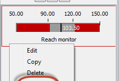
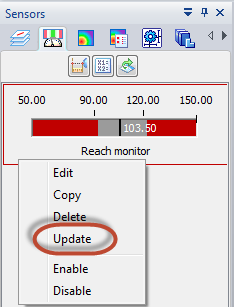
In that case you can Right-click the sensor added in the EdgeBar and select Update from the context menu.
Other options in the menu are Edit which is same as double clicking the sensor which brings up the Sensors dialog for editing parameters.
The sensor can also be temporarily enabled or disabled from the context menu or even deleted.
The sensor can be copied to additionally create say a vertical height monitor without going through the entire process of creating one from scratch.
The setup is now fully ready. Click in the Excel window and change a cell value for one of the angles. Watch how the live link updates the angle value on the relationship which moves the arms or links thereby affecting the minimum distance or Reach which is being monitored by the sensor.
Thus various features within and outside Solid Edge like sensors, minimum distance measurement, PMI, assembly relationships, the variable table and MS Excel work in cohesion creating synergy producing an effect greater than the sum of their individual effects.
Read another article about Surface Area Sensors in Solid Edge here.
~Tushar Suradkar


Comments