Simplifying Parts and Assemblies
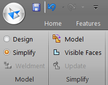 Creating Simplified parts and assemblies is one of the steps in making large assemblies that are easy to work with. The processes for simplified parts and simplified assemblies are different, so let’s go through the process for parts first.
You probably don’t want to make a simplified version of every part, not every part will need it. The goal here is to save time – mainly the time it takes the computer to display all of the faces and edges of potentially thousands of parts in assemblies and drawings. You get the biggest bang for your buck in the simplification world by simplifying complicated parts that are used frequently, so you need to go through your library of hardware and make sure the parts are not hindering your large assemblies. If you work in an environment where multiple users share the same library of parts (and face it, who doesn’t?), the effort you put into this simplification will be multiplied by every user of your library.
You may also need to simplify highly complex single parts (non-library) that may only be used once in the assembly (such as a crane arm with hundreds of tubular elements, or a single sheet metal part with a pattern of thousands of holes).
Before we start talking about how to create simplified parts, let’s first talk about what simplified parts are, and then when and why the technique is useful.
Examples of the types of geometry you want to eliminate or simplify:
- Threads
- High-count patterns
- Extruded text
- Knurling
- Faces with very small radius (edge break type of rounds)
- High numbers of round features
The simplest of all face types is the planar face. This list can help you sort out which faces would benefit the most from simplification: (the list is ordered from simplest to most complex)
- Planar (flat)
- Cylindrical (can)
- Conical or Ruled (curvature in only one direction)
- Spherical (ball)
- Toroidal (doughnut)
- Helical (screw)
- General NURBS (loft, Bluesurf, multi-section sweep, any interpolated surface type)
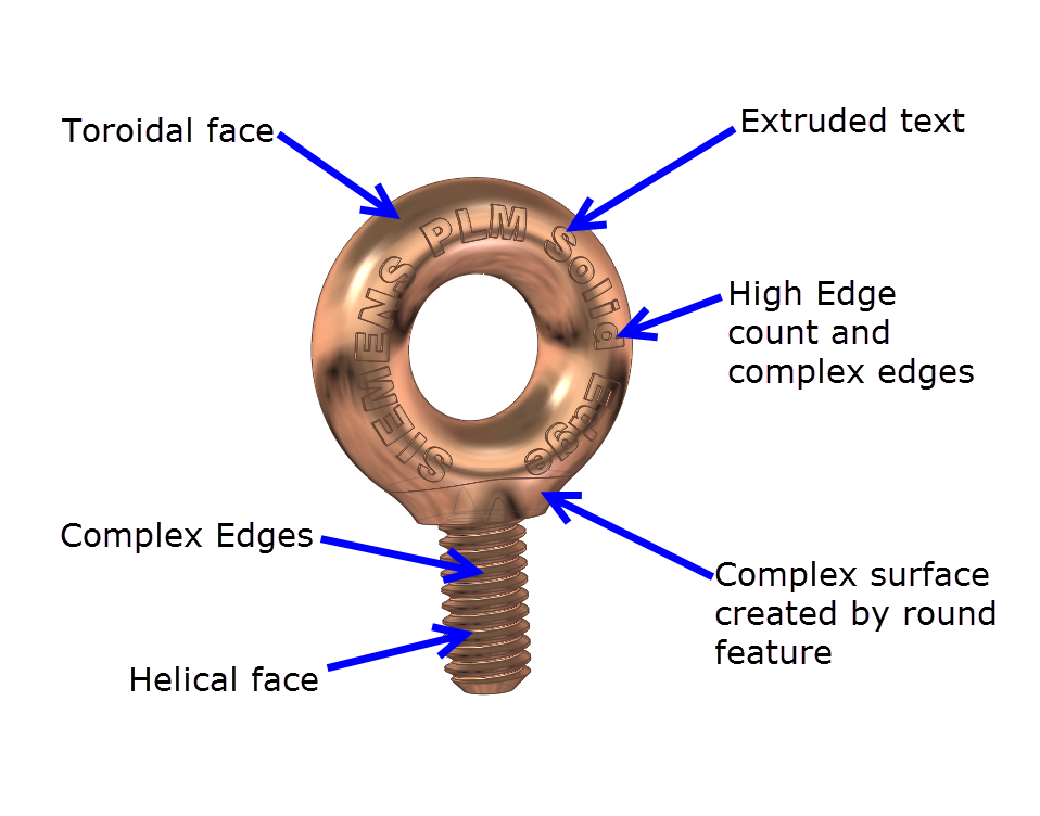
We also need to discuss edges, because edges can be displayed in the graphics window of parts and assemblies, but also on drawings.
- High number of edges
- Edges that are very small with respect to the rest of the model
- Edges with complex curvature
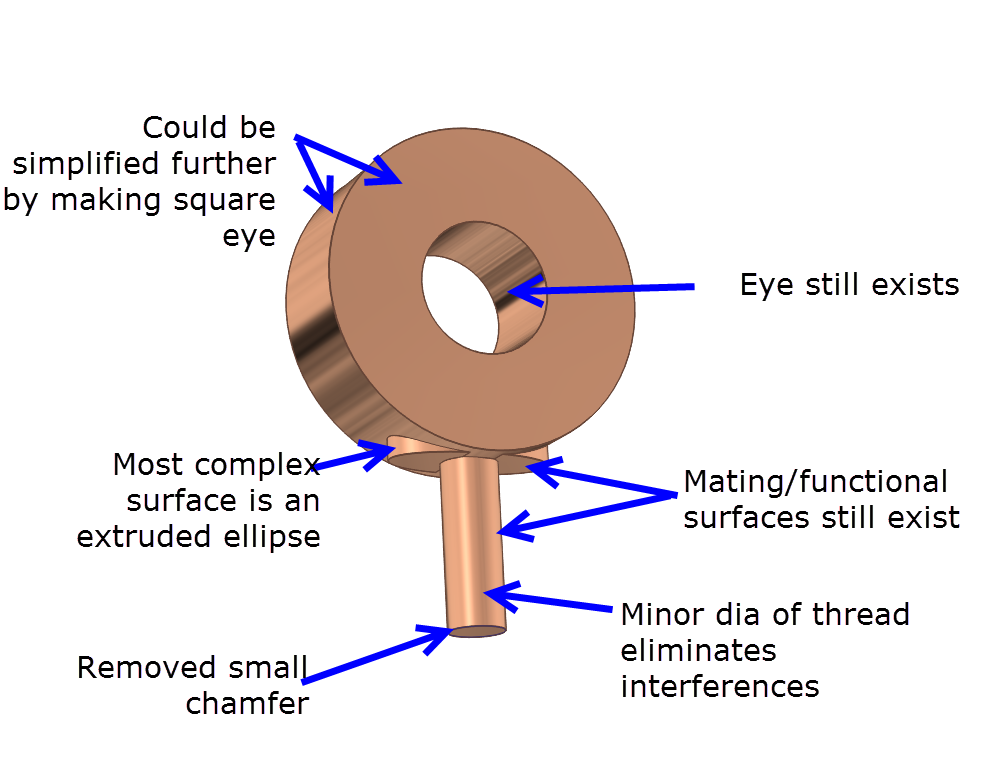
To create a simplified part on Solid Edge, you take an existing part, synchronous or ordered, change to the Simplified environment (on the Tools tab), and start adding (ordered) features. These features can add or remove material, and they only affect the Simplify environment.
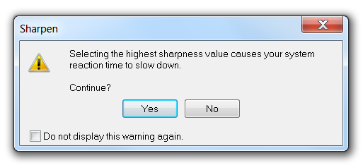
The goal of this task is to lower the face and edge counts, and to simplify the types of faces. For example, helical faces should be removed in favor of cylindrical faces. How far you go with the simplification has a lot to do with how much stomach you have for parts looking block-ish instead of round. Much like the way Solid Edge automatically handles the View => Sharpness setting, illustrated here. As you zoom out the software may eliminate some small details.


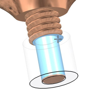 To create the simplified part, I first switched to the Simplified model environment, on the Tools tab, then I started adding features. The first feature was to cut the threads down to the minor diameter. This was done with two concentric circles. The material cut away was what was between the circles.
This cut has two affects. First, it removes the complex geometry of the modeled thread. This speeds up the display significantly. Second, it removes interferences due to thread contact. When you test an assembly for interferences, you know threads are going to interfere somewhat, so just removing these from the results can save you a lot of time on that analysis. Plus, interferences in assembly draft views can cause some lines to be missing from key views.
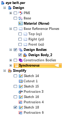 Reasons to model helical threads in 3D:
- to machine with an end mill (not with a threading die or rolling process)
- to 3D print
- to do simulation using the actual geometry
- to do photorendering
- to get highly accurate mass calculations
If you are concerned about large assembly performance, you don’t want to have actual helical threads modeled on all of your library of threaded fasteners. While that kind of detail looks impressive to the uninitiated, it’s going to cost you big time when you’re working on the later stages of a big assembly or draft. In fact, with fasteners, it is best not to have the complex version of the fastener at all, and the Design version of the part is actually the simplified version. This will also save you from changing all of the library/fastener parts to Simplified versions in the assembly.
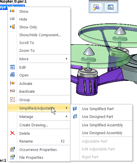
When you have parts in your assembly that you want to show in the Simplified version, just right click on the part 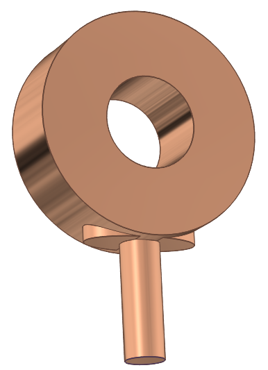 and select Use Simplified Part.
You can use all of the available multiple selection methods including selection from the Pathfinder and in the graphics window to change to Simplified versions.
The Pathfinder symbol for a simplified part being used in an assembly is the small blue triangle at the lower right corner of the yellow part icon, as shown here.

Simplified Assemblies
Notice in the RMB menu to the right, that you can also use a Simplified assembly. A simplified assembly is used in the same way and for the same reasons that a simplified parts is used, but creating the simplified assembly is entirely different.
There are two ways to create a simplified assembly:
- Model it using traditional modeling methods
- Create it automatically from visible surfaces of existing parts
An example of modeling with traditional methods to make a simplified assembly would be to create a couple of extruded blocks representing an air conditioner assembly. The blocks are the size and rough shape of the parts of the assembly, and acts as a place holder, but saves a lot of computer memory and calculation time by representing it with a single body rather than dozens of parts. You have to model the body with the same relationship to the origin as the parts have in the assembly.
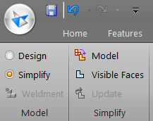 To use the Visible Faces option, there must not be an existing body created via the Model technique. If there is a pre-existing body, you can just delete the Simplified Assembly entry in the Pathfinder.
Click on the Process button, and the Modify Results interface will appear, as shown to the right. (For these screen shots, I’m using the Maximum Assistance theme, where the CommandBar is docked vertically to the left side of the screen, and is expanded with text labels for all of the icons).
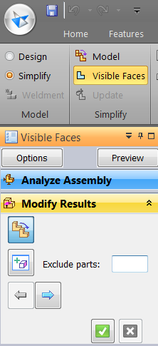
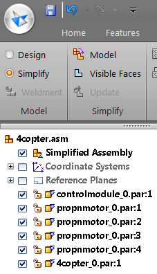
You can turn the display of parts on or off in Simplify mode, but you cannot delete parts. To delete parts, you have to switch back to Design mode. Other types of functions such as assembly motion will not be available in Simplify mode. Remember the goal of Simplify mode for assemblies is to make an upper level assembly easier to work with. You wouldn’t necessarily work directly in an assembly in Simplify mode, but you would put a sub assembly into an upper level assembly as a simplified assembly. You might also work in an assembly in Design mode with several simplified parts in it. You can get assembly motion in a Design assembly using simplified parts.
The symbol for a simplified subassembly in the Pathfinder of an upper level assembly is again the small triangle in the lower right corner of the yellow block assembly symbol.


Comments