Secondary Sheet Metal Features: Louvers and Gussets
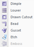 Solid Edge has a wealth of built-in secondary sheet metal features that are sure to make your life easier if you use them. There’s a lot to show here, so let’s just get started. All of these tools are found under the Dimple drop down on the Sheet Metal group. You have to have a sheet metal part open in order to see these features. For those of you more familiar with other CAD packages, Solid Edge has a separate part type for regular parts and sheet metal parts.
You might think that you would have to use Ordered mode to be able to fully edit features like these, but all of these features can be 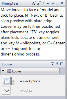 created and edited in Synchronous mode. Once you get used to using procedural features, you’ll realize that there are fewer and fewer situations where you really need to resort to the Ordered workflow.
Let’s take the Louver feature first, because it’s stunningly easy to set up. You have to start with at least a single panel of sheet metal. You can’t put a Louver as the first feature. So if the Louver icon doesn’t light up, you know there’s something wrong with your starting point.
Next, bring the cursor over the panel, and the Louver will add material on the side of the sheet metal facing you. If you want the Louver to go the other way, just flip the part over (probably easiest using a spaceball or keyboard shortcuts). You can move the Louver around and it previews where ever your mouse is.
 To spin the Louver, press N (next, counter clockwise) or B (back, clockwise). To lock/unlock the plane, use F3. If you get an error symbol, then there is something wrong with the location of the louver.
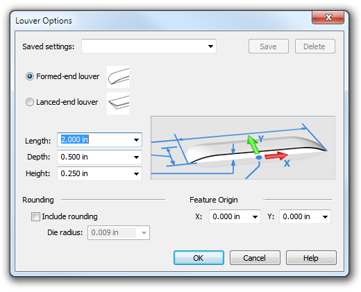
The Louver Options available from the CommandBar give you some straight-forward options, along with the Saved Settings, which allows you to save the current settings as what would be called a Favorite in other software. You can access these favorites using the drop down in the CommandBar.
In order to get the automatic dimensioning to work, you have to lock to a face (when you do this, the Keypoints icon will become active), then move the cursor over an edge, wait for the indicator, and use the M (midpoint), C (center), or E (endpoint) keys to direct the dimension.
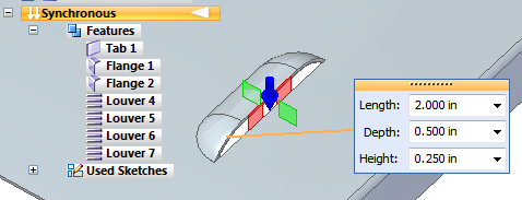
Once you have locked the plane, you can’t use the N or B to rotate the louver any more.
Once you’ve placed the louver, you can edit it by double clicking on the feature in the Pathfinder. This brings up the callout with the various dimensions that you can control.
Yes, this is still Synchronous, even though it recognizes features and feature values. It’s called “procedural features”
An alternate way to get to these values is to double click on a face of the feature in the graphics window, then select the Louver feature from the QuickPic list. This method has more steps, but might be easier if the Pathfinder has a lot of features.
Louver features can be patterned, moved, deleted, and copied like other features.
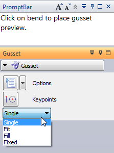
Gussets
Gussets require that you have at least one bend on the part you are working on.
The Options dialog is shown below. Again the Keypoints are to help you snap the gusset to specific points along the bend. The drop down list at the bottom of the CommandBar is for immediately patterning the gusset you create along the bend.
Let’s take a look at the Options. They will help you size the gusset and control its shape.
Again we see the Saved Settings box, allowing us to access favorite settings later on.
There are a lot of nice things about the sheet metal functionality in Solid Edge, but one of the things they could improve on is the diagram in the Gusset Options dialog. Maybe they could use labels on the diagram to make the various 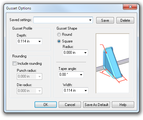 dimensions easier to identify. The Depth is the distance from the angled face of the gusset to the outside of the bend. The Taper angle is measured from the angled face to the sides. The angled face always splits the difference between the faces on either side of the bend. In most cases the faces are perpendicular to each other so the angled face of the gusset is 45 degrees. There doesn’t appear to be any way to control this in Synchronous. The Width is the dimension at the bottom of the diagram.
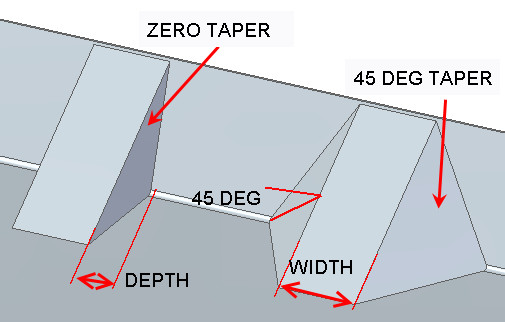
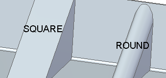
The gusset shape of Square vs Round would also be better illustrated by a side-by-side image like above, rather than the radio button toggle. The “Rounding” referred to is talking about 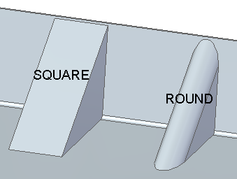 adding rounds to all the sharp corners of the gusset, illustrated below.Anyway, once you know the interface, these things are trivial, but learning it they may not be.
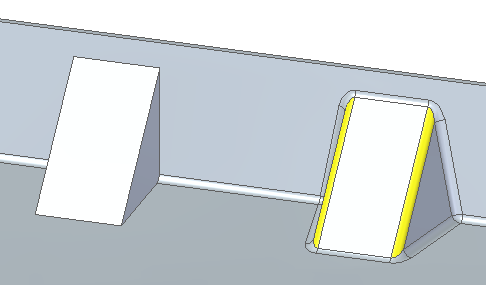
Obviously, the gusset on the right in the image below has the “Rounding” applied, and the one on the left does not. The yellow faces are not controlled by the “Rounding” option, however. They are controlled by the Radius value under the Square gusset shape option. This is far from obvious, I think. I’d consider the entire Options dialog for this feature to be low-hanging fruit for a nice enhancement in a future release.
Summary
The sheet metal functionality in these two non-sketched features is very nice. You get nice, easy to edit geometry, even with Synchronous mode. But in my opinion, the interfaces leave a lot to be desired. It could be that moving the option dialog boxes into the CommandBar would help both the ease of learning and the workflow (number of clicks). The diagrams could also benefit from some revision.
How does the “peanut gallery” feel about these tools/interfaces?


Comments