Secondary Sheet Metal Features: Dimple, Drawn Cutout and Bead
 The last sheet metal features we talked about were the Gusset and Louver. These are features that don’t require sketches. The ones we’re going to talk about today are the Dimple and the Drawn Cutout, which do require sketches. Let’s make a Dimple.
DIMPLE
The Dimple requires two things: a sheet metal panel and a closed loop sketch (or some other region area).
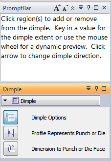
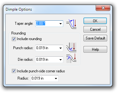
The interface for the Dimple has the CommandBar shown to the right and the Dimple Options dialog shown below. All of these settings are pretty easy to understand, and self-explanatory. Notice that these diagrams illustrating the dimensions are better done than those on the gusset.
There are some things to understand. You cannot use nested loops (one closed loop inside another – so two concentric circles cannot be used), but if you want to do a multi-level Dimple, you can make a second dimple on top of the first one. In my experiments, regions were often tricky to select, for whatever reason.
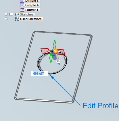 Also, unlike louvers, it looks like you can change the direction of the Dimple pretty easily. To edit the Dimple, double click on the Dimple feature in the Pathfinder. This allows you to edit the sketch (profile), direction, or the depth.
When working with the sheet metal features, the “punch” is the smaller part of the tooling, and the “die” would add a sheet thickness of material between it and the punch. Although if you’re doing sheet metal parts, you probably know this better than I do.
This editing ability that includes editing a profile for a Synchronous feature seems a little odd. I was just getting used to Synchronous feature disposing of sketches. Anyway, it seems to make sense, and works well.
Remember also that Solid Edge does not thin down the material for this type of feature in the way that a real world part would, especially on deeper dimples or drawn features.
Dimples are pretty simple if you keep in mind their limitations.
 Drawn Cutout
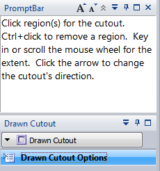
I’m not really doing this to criticize the software, but I’ve still got to call it like I see it. The Drawn Cutout is very simple to the Dimple, but it has an open face. The CommandBar for the Drawn Cutout is to the right. The only clickable part of the interface is a button for the Options. Wouldn’t it make more sense to put all of those options right on the CommandBar? It just makes another click and another awkward dialog box.
Anyway, it’s minor because the functionality is pretty good.
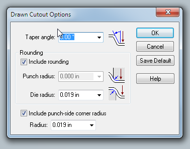 Drawn Cutout again requires a sheet metal panel and a closed loop sketch. You use the arrow to determine the direction of the material.
Just as an aside, why couldn’t you also use the arrow to determine the depth of the material? My natural inclination was to click on the arrow and pull to make the wall taller.
One other thing piqued 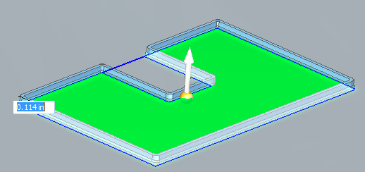 my curiosity. After the cutout was created, the cutout window was still selectable and seemed like it was somewhat shaded rather than just colored like the background.
BEAD
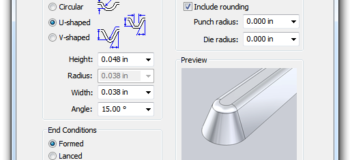
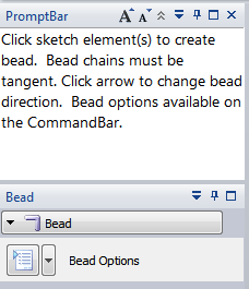 The final feature that we will go over in this post is the Bead. The Bead is like a raised rib in the sheet metal panel. It requires that you have at least one sheet metal panel in the active part as well as an open or closed loop sketch.
The Bead is another feature that has only a button for Options on the CommandBar.
This feature is so far beyond what was available in SolidWorks that all the options make me a little giddy. The end conditions in particular are a very nice touch. You could make Works do this, but it would require you to set up some pretty elaborate library features.
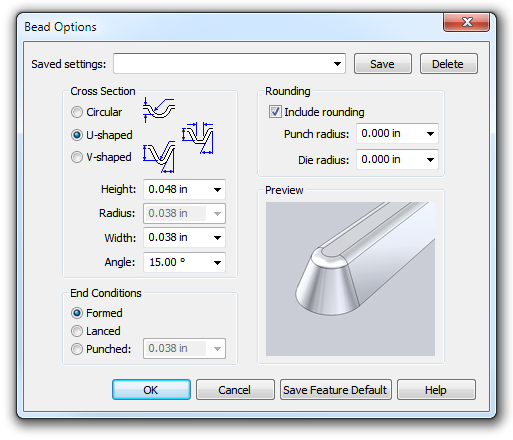 Anyway, the options in this dialog again look pretty self-explanatory.
The one thing that looks a little odd here is that the V-shaped bead actually looks more like a U, and the U shaped bead looks more like a V. Just a strange observation.
These tools are all very welcome additions to the Solid Edge sheet metal toolbox.They kind of make me wish I were a sheet metal designer. Very cool stuff.



Comments