Making Edits to Migrated Parts

Maybe you noticed that a blog written in third person starts out kind of cool, but the novelty wears off somewhere in the second article. So our story is gonna switch. The engineer that has been working in Solid Edge with imported data got promoted to engineering manager, and as a new hire, YOU (yes, YOU) now have to keep his work going. Don’t worry. I’ll help you through it.
As your new boss was clearing out his old desk to give you a place to work, he was telling you that there are a few things in the motor subassembly that need to be fixed. The in-context relations made working with the model in the old software nearly impossible. The first task you have been given is to make sure that the piston clears the counterweight on the crankshaft as the crankshaft rotates. Right now there is a pretty significant interference.
There are a couple of ways to handle this, but first, you’re going to try to narrow the cylinder between the flats to make it fit between the counterweight lobes of the crankshaft. Get 
As you look at this, you’re a little surprised. “I thought this was a translated part?!?!” You say out loud with a quizzical look in the direction of the cardboard cut out of your boss that he left in the office for you to admire. “What’s with all these features listed in the Pathfinder if it’s imported?”
Synchronous Technology has a different way of defining “features”. Since a feature is no longer something that you have to go to a dialog box to edit, it becomes just a collection of faces in Synch Tech. You’ll find that the selection is very powerful in ST, in fact, your design intent comes from the selection. We’ll explain this in more detail in a later article. At first this will seem odd, but in time you will come to understand that this method actually gives you a lot more flexibility than features and dialog boxes.
What has happened here is that in the process of taking the geometry out of SolidWorks and putting it into Solid Edge, the migration tool identified the faces belonging to each feature in SolidWorks, and made this list in Solid Edge. So if you want to delete one of the Fillet features, for example, it’s easy to do. You just select the Fillet in the Pathfinder, and delete it. This deletes all the faces associated with that feature, which will have the same effect as deleting the feature in the native SolidWorks.


Click on the Fillet6 feature in the Pathfinder, and two sets of faces light up on the model. Now press Delete. The Fillet6 entry in the Pathfinder goes away, and so do both sets of highlighted faces, leaving a sharp edge, just the way it would have happened in the native SolidWorks.
Now honestly, that’s just freaking amazing, isn’t it? So you really didn’t lose as much information as your SolidWorks using co-workers tried to convince you you were going to lose, did you?
Let’s try this again, just to make sure it wasn’t a fluke. What are some other things that you can do with “features” in SolidWorks that you might think you’re going to lose in a translation? How about the ability to change dimensions? You might not believe what’s about to happen, which is why this Piston part is attached to this article down at the bottom, you can try this yourself in Solid Edge.

Now use your mouse scroll wheel to change the dimension. Notice that the fillets fail if they get smaller than 0.177” or larger than 0.226”. As the dimension changes in the box, the actual radius on the screen changes as well. This is far beyond what history-based users expect when working with imported “dumb” solid data. At this point you realize that the solid was never “dumb”, it was just your old history-based software.
Delete Fillets 3, 4, and 5. Bang. Gone.

Now click on the white arrow, move it slightly toward the center of the piston, and enter .4 into the dialog. You may have to view the part from a slightly different angle to get the move to work easily, since the cursor is picking up things in the background to try to snap to.
Next, on the outside, Ctrl-select these three faces – the vertical flat outside face, the flat face on the tombstone shaped boss, and the chamfer inside the hole.

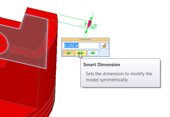
One more change and you can go get some lunch. Press ESC a couple of times to make sure you’re cleared out of any other commands. Click on the Home tab and look for the Dimension group. There should be an icon there called Smart Dimension. Click it.
Now click on two edges as shown in the image below, and place the dimension.
The .152 dimension can be changed in three ways:
- So the left side moves
- So the right side moves
- So that both sides move symmetrically

Change the value to 0.200. Watch that the wall on the other side of the part also changes thickness. So this “dumb” imported part knows that your model is symmetrical. That’s a bit of magic I’ll explain later, but for now I’ll just tell you that the magic is called Live Rules, and you can leave it on or turn it off as needed.
Thanks for your help making these changes. I’ll be back for some more help in a couple of days.


Comments