It’s all about Curvature, and Curvature is all about Splines/Curves
If you are an engineer reproducing Industrial Designer stuff, one of the first things you have to do is understand curvature. It’s a different language, and a different way of thinking about geometry. The sun rises and sets on splines, or curves. Here’s why:
Most engineers are most comfortable with lines and arcs. These are easy to understand, and easy to manufacture. They are easy to represent on drawings. I’ve heard a lot of people say they can make any shape with lines and arcs.
There are two types of shapes that really require something other than lines and arcs. The first is consumer product type shapes, and we’ll talk about why they require splines a little later. The second is ironically highly engineered products – either for some sort of airfoil or fluid flow or a real stress-optimized shape.
The reason consumer products need curves is the old marketing saying – “sex sells”. Now I’m not gonna get raunchy on you here, but biological shapes are not typically made from lines and arcs. They are represented with splines. There’s a reason why certain curves are attractive to us as humans – it’s because humans are curvy.
So what’s the difference between lines/arcs and splines?
The big difference is this: A line has no curvature. An arc has constant curvature. A parabola has curvature that varies from a 0 limit to a certain max value at the vertex. An ellipse has curvature that varies between two max/min values. A spline has variable curvature that changes as the user wants it to change, and can flip convexity from one side to the other. You can assign tangency at the end of a curve, or you can assign curvature continuity, which means that the spline will have the same curvature value at the end as whatever other entity it runs into.

Why is this important? Take two arcs. One has a radius of 1 the other has a radius of 2. (By the way, radius is the inverse of curvature, c=1/r, so that infinite curvature means 0 radius [essentially a point], and 0 curvature means infinite radius [essentially a straight line]).
Radius can be measured using a “comb” on the side of the arc opposite the center. So an arc (or circle, parabola, ellipse, spline/curve) will have little spikes on the convex side that measure the local radius.
These two arcs have different curvatures, so different radii. They are tangent, but the curvature is not continuous, which is to say that the curvature changes when you go from one arc to the other. Imagine if you drove this way. You would turn the steering wheel before you started driving, and then once the wheel was in position, you would drive without moving the steering wheel. Then come to a full stop at the end of the first arc, turn the steering wheel to a different position, and drive to the end of the second arc. This is obviously unnatural. In the real world, we have very few lines and arcs. When you really drive, you change the turning radius of the car as it is in motion, which gives you variable radius curvature – essentially a spline shape.
Here’s something maybe you hadn’t thought of. If driving a car using lines and arcs is so much more difficult, with abrupt changes in curvature, what about controlling a CNC? Would your CNC equipment actually function better or there be less wear and tear if it were driving along smooth curves rather than abrupt changes?

In the figure above, the green line is the curve, the light/dark blue curves are the curvature comb, and the light/dark blue dotted lines are what is called the “polygon” (when the spline is a closed loop, the dotted lines form a polygon). The red dots are the “edit points” that were used to create the spline, and can be used to control it directly. The light/dark blue points are the “control vertex points” used to indirectly control the shape of the spline. You can see options for these things in the Command Bar, which I have set up vertically showing text so it’s easier to know what the symbols mean.
The reason for light and dark blue lines is that you’ll notice where the curvature comb crosses the actual spline, it changes from light blue to dark blue. This is called a point of inflection, where the curvature of the spline moves from one side of the spline to the other. If the spline were W shaped instead of S shaped, you would see it change twice, so there would be two light blue areas and one dark blue area.
You can turn some of these controls on so they are always visible, or turn them off, so they are only visible when you select the curve itself.
You can add and remove edit points on a spline, but usually, when you are trying to make a smooth curve, using as few points as possible is the best option. It can be tempting to use more points so that you have more control, but the truth is that the math is very smooth, much smoother than your eye when trying to place a lot of points. Usually splines with a lot of points turn out to be lumpy. This is one thing you can use the curvature comb for – as an evaluation tool for smooth splines.


In the above graphic, you can see the difference between a spline with a lot of points and a spline with just a couple points. Note: If you try to reproduce this image on your screen, you can’t do it. For some reason, Solid Edge cannot display the edit and control points for multiple curves at the same time.
The dotted line polygon with the control vertex points is an alternate method for editing the shape of the spline. The last sections of the polygon are simply tangent to the spline, and the last blue dot on each end allows you to control the tangency direction of the end of the curve. You can think of the other (blue) control vertex points as being magnetic points that influence the shape of the spline, but do not explicitly control the position. The (red) edit points control the point through which the curve will go. You can use either method or both to control curves in Solid Edge.

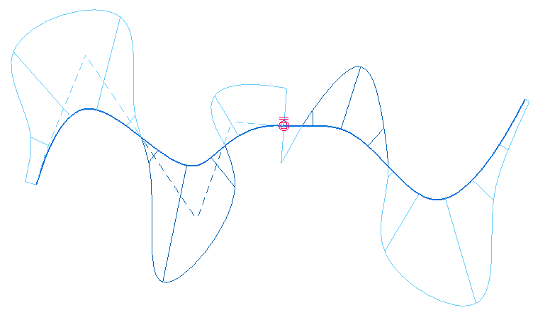
Above, you see two splines that share an end point, but they do not have any other relation to one another. If we make one tangent to the other, and turn on the curvature comb, we get the image below.
Notice a couple of things:
- The spline on the left added an inflection point (two light blue sections of the comb)
- Now the splines are tangent at their endpoints
To do this, I just used the regular Tangent sketch relation. Click Tangent tool on ribbon, click first spline, click second spline. The first spline you select is the one that will change to accommodate the new condition.
Notice also that the curvature combs don’t line up. So the splines look smooth, but they really aren’t if you think of smooth curvature using the driving analogy. The discontinuity of the curvature combs mean that the driver stopped at the end of the first spline, redirected the steering wheel, and then continued driving.

To make the curvature continuous, there is an option within the Tangent relation. First click the Tangent tool from the ribbon, then on the Command Bar, click the Type dropdown, and select Tangent + Equal Curvature.

Notice now that the curvature combs from the two different splines match in magnitude at their mutual end. There’s a catch in this. If the spline curvature combs start out on opposite sides of the splines (one has curvature up at the end, and the other has curvature down), the Equal Curvature option doesn’t understand the difference between positive and negative (light blue and dark blue) curvature. So you will get something that looks like below.

To fix this, just undo the tangent setting, manually adjust the splines so that the curvature combs are both on the same side, and reapply the setting.
Thinking like this may take some practice. Once we start getting into building some actual surfaces, you will see why getting your curves right is so important. Curves/splines are really the backbone of many types of products, and if you’re approximating with lines and arcs, your products may not be as sexy cool as they could be.