Introducing the new ST7 Hole Command
New for ST7 we have completely rebuilt the Hole Command user interface and the way hole information is stored. We’ve also added new functionality to how holes can be modeled.
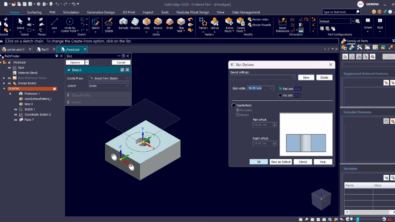
New User Interface

When you open the Hole Options dialog, one of the first things you notice is that you can now see a graphical representations of the hole parameters. As you click through the different types of holes, or change the options of the hole, the representation of the hole updates to reflect your selections. This makes defining the hole you want a more intuitive experience.
The UI still supports the usual hole types of simple, threaded, Counterbore, countersink, and tapered, with the usual options for depth control and bottom treatment. And you can still apply threads to any type of hole (except tapered).
New Functionality
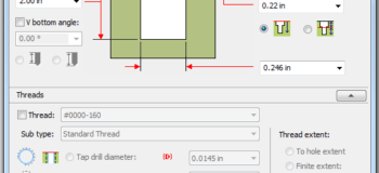
In addition to the new user interface, there are a couple of new options available through this dialog – the ability to create start, end (Ordered mode only), and neck chamfers (for Counterbore holes). With this new capability you can now add chamfers to holes as part of the hole feature itself instead of having to add them as a second feature.
Also new for ST7 is the ability to control what diameter hole is created on the actual solid model when creating threaded holes. Prior to ST7, threaded holes were always modeled at the Internal Minor Diameter. Now you have the option to have the hole modeled to the Tap Drill Diameter, Internal Minor Diameter, or the Nominal Diameter. This can be useful if you have other applications that interrogate the model and are looking for specific diameters to use to identify threaded holes.
Behind the Scenes
Perhaps the most significant change to the Hole functionality is that the hole database files are now in Microsoft Excel format instead of plain text. Microsoft Excel is not required to be installed for Solid Edge to use the database files, though you will need a separate program such as Excel or Open Office Calc to edit them.
The new format for the database files makes it easier to edit them using standard spreadsheet processing tools. Sorting, searching, and editing in a familiar spreadsheet environment will make maintaining your hole database files a snap.
Out of the box, Solid Edge now delivers 7 different database files for the following standards: ANSI Inch, ANSI Metric, DIN, GB, GOST, ISO, JIN, and UNI. These files include industry-standard holes that you can immediately put to use in your designs.
You can also create and use your own custom database files. And if you have legacy custom text hole database files, we also provide a utility ( by default, C:Program FilesSolid Edge ST7CustomHoleDatabaseConverter ) that will convert them into the new format.
When creating a new hole, most hole parameters will be populated for you based on the kind and size of hole you choose from a standard. But of course you can always manually override any parameter if desired. When you do this, the field with the override value will turn yellow to alert you to the fact that you are using a non-database-driven value for that parameter.
We hope that you find the new Hole interface and databases easy to use and that it provides a faster, more intuitive way to create holes in your designs.
Steven Sheldon
* Opinions are my own