Interpolation is the Name of the Game
My method of explaining the rather wide reaching topic of surfacing is to start from concepts, move on to how to use specific tools, and what the tools do, and then to talk about why or in what situations you might use the tools. So Concepts, Tools, Strategies, Evaluation. Concepts we are in the process of covering. Tools are what this post is mostly about. In Strategies, I’ll take an actual example that strings together several feature types and talks mainly about how you make decisions on what tool to use in which situation. And Evaluation, of course, helps us be a bit self-critical to understand what we have done and whether it is good or needs improvement.
Surface modeling is a tedious endeavor. Instead of making 6 faces at once when making a solid, you have to build things one face at a time, and then trim and stitch it all together manually, and hope you’ve done it right. Add to that complex shapes where each face has a whole world of new challenges. Feature count can get incredibly high. Feature mortality on change can be frustrating. But, “That’s Wizard’s Chess”, as Ron Weasley so famously said.
It’s a lot of stuff to learn.
If you’ve been reading this series, the last post talks about splines, because in Solid Edge, we have to start from splines to get nice surfaces. So in this post, we’re gonna talk about those nice surfaces. What types of features do we have to work with? Which ones do we rely on a lot, and which should we use more sparingly?
- Extrude/Revolve
- Bluesurf
- Swept
- Bounded
- Redefine
- Ruled
The first thing I want to make clear is that when we are talking about surfacing in Solid Edge, we are talking about an Ordered workflow. We have to sketch the features, or use existing edges. I have this recurring dream where Solid Edge gets some brand of Synchronous Surfacing. Until/when/if that dream is ever realized, our surfacing efforts are going to be limited to the sketch-and-build scheme. It’s not a bad method, but, in my opinion, Synchronous, which is a fantastic tool for prismatic solids, only reaches its best potential when turned loose on organic shapes. I’m not basing these statements on any knowledge of future development, just my own opinions.
Anyway, the main thrust of this article is to talk about the surface types available in Solid Edge today. The list above numbers the surface types in the order in which you’ll probably use them. All the types after Extrude/revolve are what I like to call “interpolated” surfaces. You probably won’t find this term in the official SE documentation, I just use it because I think it helps describe how the surface types function.
“Interpolated” is a word that could also be used to describe splines. You put down points, and a curve is interpolated between them. These complex surface types are really just two directional representations of splines. In a spline, the curve is interpolated between points. On a Bluesurf (more commonly known as a loft in other software), the surface is interpolated between splines. Solid Edge, and all modern CAD software are built on some specific math that does that interpolation for you. I’m guessing here a little bit, but I don’t believe that all CAD packages use exactly the same math by default, so I would guess that it’s probably a fool’s errand to try to exactly replicate a spline from one CAD software package to the next simply by getting all of the edit points in the right places. And by extension, trying to build surfaces exactly the same from input curves would probably yield only approximate results, particularly if you use end conditions other than defaults. We’ll get more into the details of this later, I only bring this up to reference back to the main reason I’m writing this – when you as an engineer have to recreate “swoopy” shapes, what kind of results should you expect? Again, a question that will be more fully answered in due course.

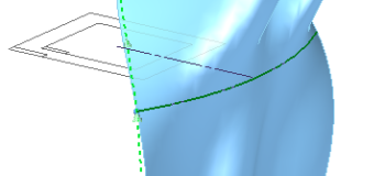
Here’s an example. This single Bluesurf uses only two sketches – a line at the bottom and an arc at the top. Ignore all of what I said previously about lines and arcs, this is meant to be a simplified example. There is plenty of time to get fancy later.
See how the vertical sides are straight lines. These simply interpolate from one endpoint of the line to one endpoint of the arc. In fact, all the vertical direction lines shown on the surface are straight, because you are only interpolating between two entities. On a graph, if you place two points, and draw a line between them, it’s a straight line.

But now see what happens when I add a W shaped spline, so the Bluesurf has to interpolate between 3 curves. This is what is meant by interpolation – changing gradually between one shape/position and another.
Further, you can control end conditions. So at the top instead of just accepting the default (natural), I’ve changed the flag up there to Normal To Selection. Notice this determines the direction of the surface as it leaves the top sketch, so there is a little bulge at the top of the image below that doesn’t exist in the image above.

I’ll go over the specifics on how the Bluesurf, Sweep, Bounded, and Ruled work tomorrow. Just for today make sure that you’ve got the concept down about interpolation, and the fact that splines are interpolated points, while surfaces are interpolated splines.


Comments