Building the Podracer Model

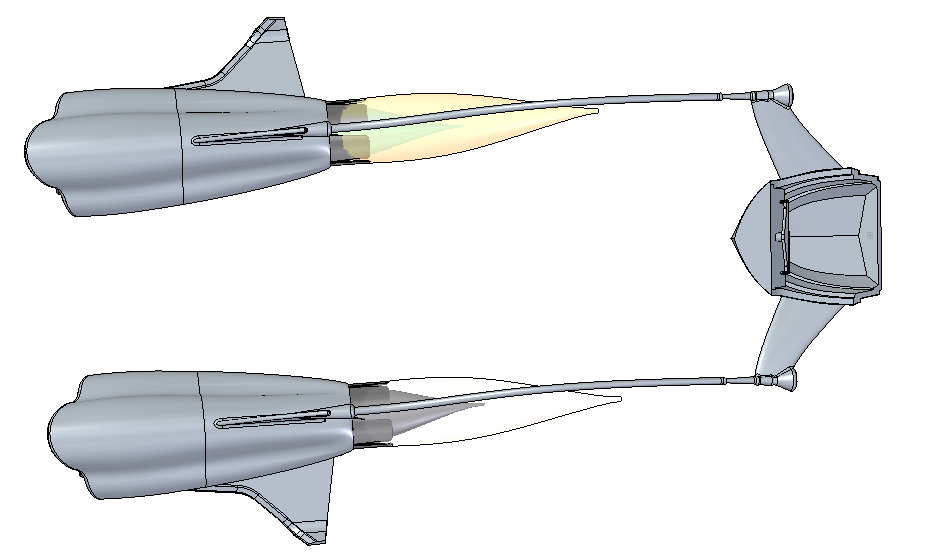
I sometimes get questions about methods I’ve used to make certain models. My recent podracer for the rendering contest was one of those models.

I need to start by saying that this model was for fun an entertainment, it’s not a production model. Add to that I’ve got other things to do, like most of you, and I had to set priorities. This limits how much time I could spend on the model. So the choices I made creating this model weren’t all based on how to make the model perfect, but how to make the model as good with as much detail as I could within the time I allotted for the task.
I feel a disclaimer has to accompany the model because when I was doing consulting, I would strive for complete perfection. So in areas where I accepted imperfections in the model, I’ll say why, and what I might try to improve it. I think exercises like this where we share our decision making process are important, because why we choose what we do is often as important as what we choose.
When I started the model, I intended to create all sketches in Synchronous mode, and all surfaces or complex shapes in Ordered. This is a technique I like, and needed another example of why it’s better than just sketching in Ordered. Sync sketches can be edited using Sync techniques while you’re still in Ordered mode, which makes sketch editing very easy. Complex shapes, however, must all be created Ordered or there is no way in Solid Edge to edit them.

I started with the left engine. There are a lot of different ways this could have been done, but I didn’t want the back of the engine to affect the shape in the middle, so I did the front-to-middle as a solid loft with three separate sketches. Actually, I just copied one of the sketches twice, and offset the middle one. If I had been smarter, I would have converted the sketch to a curve, but as it was, I left it all arcs. These sketches are all Synchronous.

I used a solid loft because I didn’t need a surface, and I didn’t need any fancy end conditions.
My first mistake comes in my second feature. This was created as a Bluesurf because I wanted a fancy end condition. I Bluesurfed from the 3 lobed arc sketch to an ellipse, and used the Parallel to Section option (which doesn’t exist in software I’m familiar with) on the ellipse end, and Tangent Continuous on the lobed end. My mistake was not converting the lobed sketch to a curve. If you look close on the finished model, you can see a couple of hard ridges in this section. Bad modeling that I wouldn’t normally let go.

The Bluesurf has some interesting options, in addition to the Parallel to Section. I also used the End Capping to close the ends. This allows you to essen tially make a solid from a Bluesurf feature all in one step on the fly. Excellent option. Again, not found in some other software.
To make the exhaust nozzle fins, I first extruded the ellipse as a surface. Notice how each sketch serves double duty. Then I created a couple of trim surfaces to trim out sections of the extruded ellipse.
I wish you could trim with just sketches, but sketches must lie on the surface. So you have to go through the steps of extruding the sketch, and then trimming with t he extruded surfaces.
Then I got distracted by the front of the engine again. You know how they say design is not a linear process? Especially when you throw a little ADD in there. I cut out the cavities for the 3 turbines, and then made a rotor cone. The rotor cone pattern would be easy in Synch, you just copy, copy, copy. But in Ordered, this was an ugly mess. I used a table driven pattern to make the 3 cones, and then (the ugly hack) used Move Face to move the 3 faces of the top cone forward. Someone may suggest a better way to do that, or a more proper way, in any case, but this just shows how Sync-like even my Ordered thinking has become.
Of course before I could pattern the cones, I had to make the turbine blades, which were just flat surfaces tilted at an angle, and trimmed to shape. Because the middle one was bigger, I made all the blades too big, then trimmed them back as 
 needed.
As an aside, ST6 improved the way Solid Edge handles bodies significantly, but I have to say that I don’t understand it fully yet. There is a lot of functionality, much of which I might not yet appreciate. Very often, things that look like separate bodies to me are treated like a single body with separate “lumps”. This can be handy sometimes, especially to avoid a lot of repetitive operations.
Returning to the back of the engine, I used the Thicken command to solidify the nozzle fins. Here you can also see the hard edges created by the Bluesurf.
The flames out the back are just translucent surfaces. Coloring these in Solid Edge is problematic because of the concept of “active body”. You can’t control colors the way you can individual parts. Instead of relying on bodies so heavily in this model, I should have used parts in an assembly.
 I created the other engine by inserting a part copy and mirroring it along with all of the surface bodies. This wasn’t as easy as I wanted it to be mainly because mirroring the solid and surface bodies all at once was a little quirky. I was eventually able to get everything selected, so it showed up correctly at least once. There is the Last Saved option in the Show/Hide Component dialog which helped me take it where I wanted it to go.
T here needs to be a big spark connection between the two engines, and the best way to do this is probably to sweep a shape, then wrap a lightning bolt image onto it several times. Modeling something that erratic would probably not look great.
Next is the chariot, or cockpit or whatever you want to call it. I made mine shaped like a boat because of the recent discussion on the forum about how to create a boat hull.
In the past, I would have created the side faces of the boat hull all in one feature, but in Solid Edge, I had to take a different approach. Each face was created individually, and each edge also had to be created individually. I think I would have been able to avoid this if I had created the stepped sketch of the side as a single curve rather than as a set of arcs and lines. Guide curves only act “up to next sharp” rather than across the entire sketch, so I think a curve would have worked here.
 Anyway, mirroring and capping the surface worked as expected, so I was able to solidify and then shell the shape properly. I did have some difficulty mirroring the wing separately, so I had to rearrange things so that the wing and the hull were all mirrored at once.
Of course when I put the chariot into the assembly, I noticed it was the wrong scale. So I had to take it through the intermediate stage of inserting a part copy, scaling it there, and then putting that into the assembly.
The connections between the chariot and the engines used inter-part copies and a loft with some tangency controls.


Comments