Maximizing the Benefits of Electromechanical Collaboration in PCB Design

By now, everyone should know how electromechanical collaboration can increase productivity. Thousands of articles have been written over the past twenty years touting its benefits. Where electromechanical collaboration really shines, in my opinion, is when it’s used in the development of electronics. Introducing the printed circuit boards (PCBs) that run electronics into a design adds a whole new level of complexity that can’t be addressed without strong collaborative efforts.
It’s the rise in electrical content in traditionally mechanical devices that drives the need for a collaborative MCAD-ECAD environment because when you get something wrong in either environment, it affects them both; both development efforts can suffer. However, new software solutions that automate electromechanical efforts can help address product complexity.
Product developers need collaborative tools that allow different domain experts to talk to each other in real time, rather than finding errors using physical prototypes or during manufacturing, then having to send a design back for rework. A tight collaborative loop between electrical and mechanical domains enables a cohesive design process, resulting in fewer rebuilds, increased quality and faster time to market. A fully digital twin of the complete product can reduce the need for costly prototypes and enable rapid evaluation of design changes. And, advanced design automation liberates engineers from the drudgery of manual tasks, setting them free to innovate and spend more time creating great products.
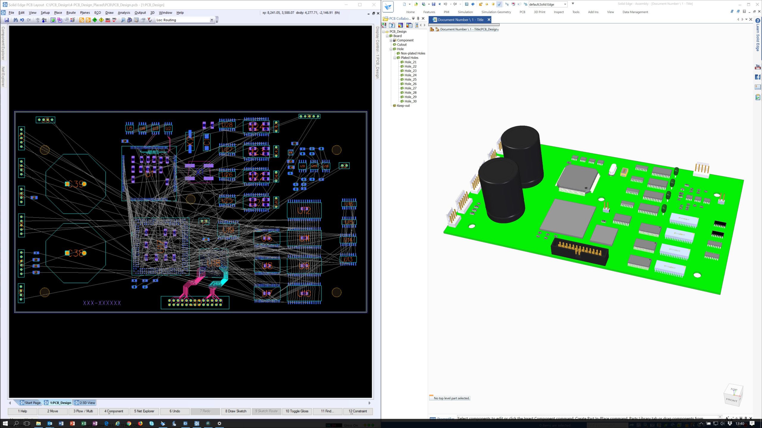
Being able to visualize components on a printed circuit board (PCB) is extremely helpful. Today’s software enables users to consider form and fit issues early in the product design process by creating a 3D model of the PCB. More than merely an interpretation of 2D information, 3D models are created for photorealistic visualization of a complete PCB design. With this information collisions between different components on the PCB can be detected at an early stage. If a collision is detected as you move a component, the software can alert the user of the collision.
Solid Edge PCB Collaboration software provides seamless collaboration between 2D ECAD and 3D MCAD design environments. It provides users with a consistent and continuous communication channel that keeps design teams synchronized as they work in their own areas while ensuring the use of up-to-date and accurate data. At any time throughout the design process, the user can preview and consider design proposals, then accept, reject and counter-propose design proposals between disciplines. The software also reduces costs by avoiding design rework on either the ECAD or MCAD side when interferences are detected between the PCB and its mechanical enclosure.
For more information on electromechanical collaboration, please download our eBook, “Benefits of collaboration in PCB design.”
For more information on Solid Edge Electrical Design software, please visit www.siemens.com/plm/electricaldesign


Comments