Custom Shape Springs in Solid Edge Part 2
 Hourglass and Barrel Springs
Start with a new part  by clicking the Solid Edge Application Button > New > Part.
On the Ribbon bar, take the Tools tab and from the Model group, select Synchronous.
The feature PathFinder updates to reflect this.
Start Line  and hover the mouse over one of the vertical planes – Right (yz) or Front (xz)
 When the plane highlights, click over the small lock icon as shown in image to lock the plane for sketching.
Draw a vertical line 100 mm beginning from the Origin.
Key-in 100 in the Length box on the Command bar and move the cursor.
 A pink line starts appearing as you move the cursor. Move the other end point of the line till you see the vertical alignment indicator as shown circled in image besides. To show such relationship symbols or not is specified in the Intellisketch Options
  dialog’s Relationships tab found in its group on the ribbon bar.
Click to place the line which is 100 mm and vertical in the xz Base Reference Plane., then click this icon  found on the right side of the screen to unlock or release the sketching plane.
 Similarly, draw a Rectangle by two Points
  in the Top (xy) plane. Key-in the Width as 50, height as 2 and Angle 180. Apply a Smart Dimension
  if required. Your sketch should now look as shown on the right. The rectangle can be connected to the origin or away from it leaving some.
 From the Surfacing tab, Surfaces group, select Swept
 ![]()
For the Path step, select the vertical line. Click Accept  on the Command bar or right-click or press <ENTER>.
For the Cross Section step, select the rectangle.
Don’t Finish the Swept command yet. Click Sweep Options on the Command Bar and in the Twist area, specify Number of turns as 12.
Click OK in the options dialog and Finish the Sweep command. The surface should form as shown.
 From the feature PathFinder, check OFF the Sweep1 surface to hide it.
From the Sketching tab, Planes group, select Coincident Plane  and select the Top (xy) Base Reference Plane from the PathFinder. A new plane appears with the Steering Wheel active.
Drag the vertical primary axis of the steering wheel 50 mm up.
Similarly, create another plane parallel to the last created plane at distance of 50 mm above.
 Start Circle
  and lock the Top (xy) Base Reference Plane for sketching.
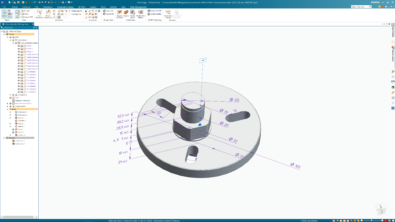
Set the circle diameter to 100 and centered about the Base.
On the middle plane, draw a concentric circle of diameter 50 mm.
On the top-most plane draw another concentric circle of diameter 100.
Use Ctrl+T or Ctrl+H  to switch to the Sketch View.
 Start BlueSurf
  and select the three circles in proper order to create the BlueSurf as shown below.
Next check ON the Swept surface from the PathFinder to make it visible and start Intersect  from the Modify Surfaces group of the Surfacing tab.
Select the Swept surface and the BlueSurf one after another and click Accept

In the Trim and Extend Step, select the two surfaces of the swept surface formed by the far and near sides of the rectangle’s shorter side.
You can use the QuickPick  to choose the surfaces needed. Click Accept and the resultant trimmed surface should look like as shown in image.
Hide the Swept surface again and you should see whatever is left of the the BlueSurf – a thin sliver as seen in image below.
 Start Derived Curve
  from the Curves group of the Surfacing tab. Pick an edge of the BlueSurf to create the curve.
Hide the BlueSurf too and all that is seen is the derived curve – a path for creating a Swept protrusion.
Create a a Plane Normal to Curve  by picking the derived curve first and then one of its endpoints.
Create a Circle in the new plane with its center at the pierce point of the curve with the plane.
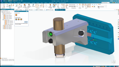
 From the Home tab, Solids
  drop button, start Swept Protrusion
  and use the derived curve as path and the circle as cross section to create the spring in the shape of an hourglass.
The Barell type spring can be similarly created by using smaller circles at the ends and a larger circle in the middle.
The idea is to intersect a helical surface with a surface of desired shape of the spring.

Creating a Tablet Spring
In Tablet springs the coil of wire winds square about the axis instead of a circular fashion.
Thus a Tablet spring is square/rectangle shape winded using stainless steel and is mostly used in tablet, capsule blister packing machine in pharmaceutical industries.
The tablet spring can also be created using technique similar to the one described above for hourglass spring.
This involves using two identical rounded rectangles instead of circles to create the BlueSurf.

To create the tapered tablet spring create a BlueSurf between two rounded squares or rectangles which are of different size as shown besides and intersect it with the helical or twisted surface
The other steps remain identical. Again the possibilities are endless.

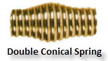
Look at the double conical spring shown besides. Think how you can model it in Solid Edge using the techniques demonstrated so far.
Post below pictures of your creations in the comments area.

Comments