Tips and Tricks from Forum Users #18

Here’s another meticulously crafted set of your own Solid Edge tips and tricks illustrated with images and animations.
Here’s a quick list of the previous compilations:
T&T #01, T&T #02, T&T #03, T&T #04, T&T #05
T&T #06, T&T #07, T&T #08, T&T #09, T&T #10
T&T #11, T&T #12, T&T #13, T&T #14, T&T #15
A collection of hidden tips and tricks from Accepted Solutions on the Solid Edge user forum.
Due credit is given to respective contributors.
1. I am a SolidWorks user new to Solid Edge and want to know:
(a) A quick way to check if parts in an assembly are fully defined? and
(b) How to use reference planes when applying assembly relationship for a part?
The Tip: A glimpse at the pathfinder will tell you this right away.
For example in the image below, note the difference in the icons for the two Splate.par, the first one is fully positioned while the second one is not.

 Note: Also see the first tip in this 16th set of tips which shows an animation of how to further check the relationships already applied.
For the second question, when inserting parts or sub-assemblies press the ‘Assemble – Construction Display’ button. Here you can temporarily activate the visibility of reference planes besides coordinate systems, surfaces and so on.

Another option would be to turn ON the visibility of planes during inserting of parts from the Solid Edge Options, Assembly tab. This is a global setting and will apply to every part inserted into the assembly.

Yet another recently added option is to RMB in the Parts Library and select the menu item to show/hide the reference plane. This applies to all parts drag-dropped from the Parts ibrary from there on.

Contributors: @David_McMahon, @hawcad and @GregLuckett
2. The ‘Extensions’ box is checked ON in my IntelliSketch options but I am not able to dimension between virtual intersections of lines. What could be the reason ?
The Tip: Intellisketch options control and/or filter selection of entities, be that geometry creation or dimension placement. The trick is, you need to mouse over the two edges that need to be extended as shown in this video:
Contributors: @SeanCresswell and @Craig_H
Video by: @Craig_H
3. How can I hide all the centrelines in one go in a drawing view of a assembly containing tubes ?
The Tip: You can use two methods to accomplish this:
After a view is placed – using a query on the drawing view.
Before a view is placed – changing the global options.
The following video illustrates both techniques:
Contributors: @Johnson_BigMatt and @hawcad
Video by @Tushar
4. I’ve been exporting multiple solids from another CAD program as one STEP file, then opening as a .par file in Solid Edge.All of the closed surfaces are interpreted as one Part Copy. Is there any way to have Solid Edge preserve the different bodies and open this file with distinct multiple design bodies rather than merging them into one Part Copy?
The Tip: In your STEP import file selection dialog, click the Options button after selecting STP file anduncheck the option to Boolean Solids.
Also in the Solid Edge STPreferencesTranslators folder there is a file called STEP.ini which controls step translation with a parameter called ‘Import Multiple Bodies As Single Part file’ that you could check and change to OFF.
Contributors: @KennyG and @bshand
5. I see there is a Trim command for surfaces. Is it also possible to un-trim the surface similar to such a command in CATIA ?
The Tip: You can do this using the Copy Surface command but only if the original surface has the required information. Select the option Remove External Boundaries as shown in the video below:
Contributor: @hawcad
Video by: @Tushar
6. When I draw a rectangle or circle, I have to enter dimensions, why do I have to go back and add that same dimension? Is it possible to auto-populate/dimension the same way I built it?
Just seems a little weird to enter dimensions twice…build a rectangle, put in the dimensions I want, and then go back and dimension those same lines.
The Tip: Solid Edge gladly supports this and you need to simply turn on a time-saver option called Auto-Dimension. This command is truly spectacular and here’s a quick video.
Also you can set this option in the IntelliSketch dialog on the Sketching tab of the ribbon bar.

Contributors: @KennyG and @bshand
Video by: @Tushar
7. I want to create a data plate for a device in which the text is cut out. My problem is that when the part is redrawn, it takes a lot of time. Are there any methods for creating texts on a part which can be shown on draft? Though cutting is an obvious method that comes to mind but it is not necessary as long as I can show it in the drawing.
The Tip: The part takes a long time to process due to a huge number of edges created during the text cutout. You could leave it as a sketch in the model or if it is a Sheet Metal you can use the Etch command, which is then suitable for laser etching, etc.
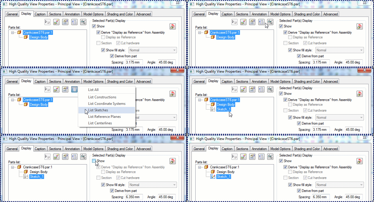
Both methods can easily be displayed in the draft, via the view properties. Select the Parts List Option button to see all options, click on the sketch you want to display in that view, and check the box to Show as demonstrated in this animation:

Contributor: @SeanCresswell
Animated GIF by: @Tushar
8. In synchronous, is there a way to combine identical hole instances from different hole features into the same feature ? Also, do you know of a quick and easy way to convert Hole features to simple features ?
The Tip: First convert the holes to surfaces or more preciselya face set and then run the hole wizard. It will recognizes these ‘free’ holes and build a new combined hole feature.
Second part of your question is also answered in the process. Here’s a short video:
Contributor: @hawcad
Video by: @Tushar


Comments