A Novel Approach to Reducing Heatsink Mass Whilst Preserving Thermal Performance, using FloTHERM
Heatsinking is a common method to facilitate the removal of heat from a dissipating component, thus reducing source (junction) temperature. More an ‘area extender’ than a heat sink, the heat is offered up to a much bigger surface area for removal by air than would be available from the top surface of the IC package alone. High thermal conductivity metal is used to construct the heatsink so as to easily conduct the heat to all parts of its surface area. Not all portions of the heatsink work with the same effectiveness however. Some parts under perform and so there is an opportunity to identify those portions and remove them so as to save weight and cost without unduly affecting overall thermal performance. The question is how to identify those portions.
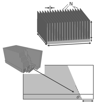
The topology of a heatsink is usually very simple. Due more to manufacturing constraints than the ease by which it might be designed. Extruded plate fin type heatsinks require parameters such as x, y, z overall size, base thickness, number of fins, fin thickness etc. Classic simulation based DoE, response surface and gradient based optimsation approaches can then be used to identify a combination of those parameters that best meet thermal design goals.
For this study I’ve used FloTHERM to pre-optimise 2 heatsinks, one for a forced convection operating environment, the other for natural convection, cooling a single heat source:
 Thermal engineers reading this will have noticed that I’ve modelled half the heatsink, utilizing symmetry conditions at the center plane of the heatsink.
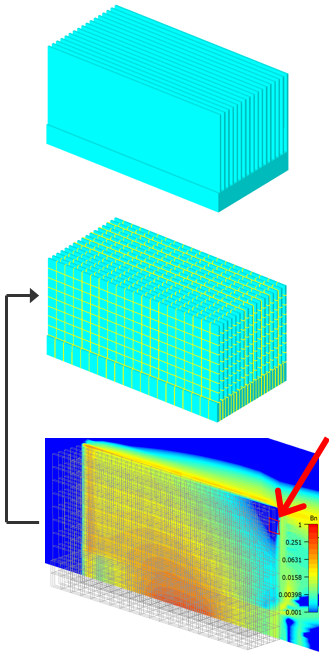 A novel method has been developed to sequentially remove mass from the heatsink from locations that are identified as being thermally least important. These areas are taken to be those with the smallest thermal bottleneck. The areas are set by discretising the heatsink geometry into a tessellated collection of small chunks. Removal of such lowest thermal bottleneck areas, a resimulation of the remaining geometry and a repeating of the process leads to a graph of the increase in thermal resistance of the heatsink vs. the reduction in mass being created. The thermal resistance is going to trend upwards, you can’t expect removal of such geometry to have anything but a detrimental effect. The value though is to identify what the relationship is and to observe if there is opportunity to remove enough mass without incurring too big an increase in thermal resistance.
The following animation shows the results of the sequential removal process and the graph of % increase in Rth vs. % reduction in heatsink mass. First for the forced convection case:
 It’s clear that there is not a linear relationship between removed mass and increase in Rth. So not all parts of the heatsink are equally important. In fact for this forced convection case 30% of the mass can be removed with only a 10% increase in Rth.
Identifying the lowest thermal bottleneck chunk to be identified anywhere in the heatsink results in topologies being identified that could not be manufactured using classic methods (milling, casting) though of course metallic 3D printing could be applied. Constraining the removal from just the top of the fins (or top of the base) was implemented so as to provide insight into millable or castable topologies:
 Similar trends of the persistent important of the outer fin and the less than optimal central fins on the downstream side are noted. With this constrained removal a 10% increase in Rth is seen with a 25% reduction in heatsink mass.
There is greater scope for removal of inefficient portions of the heatsink under natural convection cooled conditions. Again, with unrestricted portion removal:
 There is hardly any increase in Rth for the first 10% of mass removal. In fact Rth decreases very slightly at 5%, contradicting the assumption made above! This due to a decrease in surface area and friction drag promoting an increase in mass flow rate that more than counters the decrease in available heat transfer surface area. A massive 42% of the heatsink mass can be removed with only a 10% increase in Rth!
Again, similar trends are seen when constraining the removal from the ‘top down’:
 Much of the base is initially removed, with just enough base left to pass the heat to the peripheral fins. This time 35% of the heatsink can be removed suffering a 10% increase in Rth.
 This methodology provides insights into new mass efficient heatsink topologies. These insights themselves may be captured in terms of additional geometry parameters that could be added to an overall parametric description that then could be optimsed using more classical approaches.
The mass removal method presented here was implemented using FloTHERM’s ‘FloSCRIPT’ automation technology, the sequential process being monitored by a VBA script that identified the lowest thermal bottleneck portion, removed it, resimulated and repeated. Such automation could be applied to any heatsink geometry.
In all though this is a good example of how FloTHERM simulations can be used for far more than just predicting operating component temperatures. Simulation provides deep insights into the behaviour of a product concept and offers many opportunities to derive a better product design as a consequence.
Want to find out more about FloTHERM’s capabilities when it comes to heatsink design? Why not register for this forthcoming updated version of our Heatsink 101 presentation, on 9th June 2016:
https://www.mentor.com/products/mechanical/events/heatsink-101
It’s even got its very own trailer!
23rd May 2016, Ross-on-Wye.