Top 10 FloTHERM V10 Features – #8: Thermostatic Control with Hysteresis
Electronics thermal simulation historically focussed on steady state conditions, worse case scenarios where for example a power dissipation is assumed at a maximum and unchanging. Not a direct reflection of reality but the conservative (over)temperature simulation results enabled design margins to be implicitly factored in. Over the years, as margins reduced and the need for ever more accurate simulations increased, the proportion of transient simulations that FloTHERM conducted has increased dramatically. From a FloTHERM development perspective we’ve kept on top of this trend. An overhaul of our transient definition capabilities in V9.1 has now been followed by substantial changes in our transient modelling capabilities in V10.
Beyond standard transient considerations such as the thermal response of a system to fan failure condition, or a cold start power on, thermostatic control is an approach that can be used to both limit operational temperatures and lower power usage. Various user posted feature requests on the Mentor ‘IDEAS for Mechanical‘ site alluded to this, all of which have now been satisfied by a couple of new V10 features.
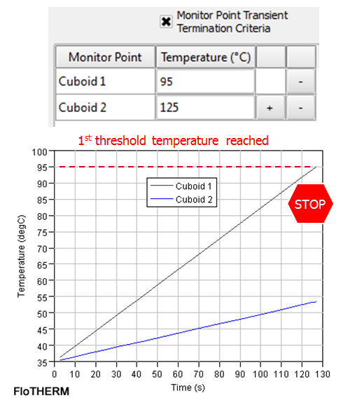
 The ability to stop a transient solution, automatically, is now available via a new ‘Monitor point transient termination criteria’ option. One or more monitor points can be nominated, with individual stopping criteria temperatures. During the transient simulation, as soon as one condition is met, the simulation automatically stops. This allows inspection of the model at that time/temperature, results exported or manual modifications made to the model and solved onwards.
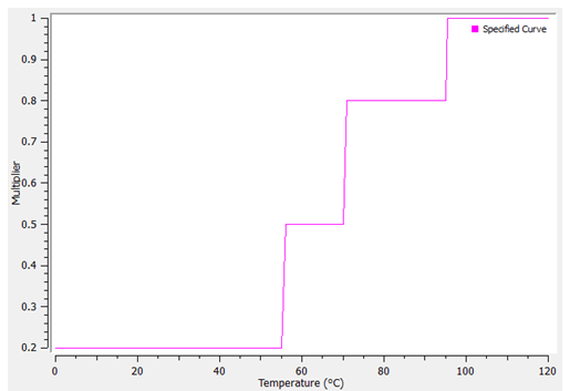
The real doozy though is an extension we have made to the transient attribute. The transient attribute is a curve that relates a multiplier value with time. This attribute can then be attached to a power dissipation value, a temperature etc. to vary those boundary conditions (BCs) in time. In V10 we have added the option to also include a multiplier vs. (monitor point) temperature curve as well. In this way a BC can be varied in time AND/OR as a function of temperature.
 Very powerful, especially when considering the application to die level models where it would allow for a transient variation of the switching power portion and a temperature dependence of the leakage power portion of the power dissipation together.
 And there’s more…
  Thermostatic controlled fans are very common, especially in consumer/laptop type products. Ever hear your laptops’ fan come on when the CPU gets too hot running all your FloTHERM simulations? In V10 you can now attach a transient attribute to a fan to affect its RPM derating factor during the transient simulation, either as a function of time or monitor point (hub mounted or remote) temperature.
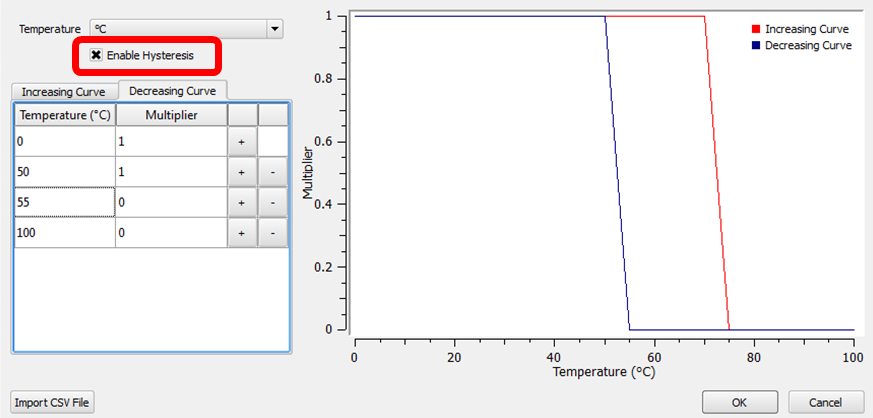
 And there’s more… In addition to a single curve relating the BC with temperature, a Hysteresis option can be checked to allow two curves to be defined, one controlling the BC when the temperature is increasing, the other to control the BC when the temperature is decreasing.
Accommodation of such hysteresis allows for better tuned thermostatic control methodologies to be investigated and determined in FloTHERM. If you want to leanr more about such control, here’s an interesting piece from Panasonic comparing and contrasting PID and Hysteresis control approaches.
As you can hopefully see, the FloTHERM development team are big fans of transient simulation technologies 🙂
29th August 2014, Ross-on-Wye
p.s. let’s hear it for Jimmy Cricket!


