Top 10 FloTHERM V10 Features – #6: Integrated Summary Columns
If there’s one word that describes electronics products it’s ‘complexity’. Actually, scratch that, that’s too generic a term. How about ‘cluttered’? IC packages are constructed from a number of different parts, soldered onto a PCB that is constructed from a series of layers and secured into some kind of chassis. ‘Packaging’ at various levels, physically interconnecting functionality with itself and to the outside world. From an electronics thermal simulation perspective such an application is not complex in terms of advanced physics and convoluted curved geometries but it does entail specific challenges for those involved in assuring thermal compliance.
 There are only about a 3 orders of magnitude difference in the thermal conductivities of the materials that go to make up an electronic product. ‘Only’ when compared to a 12 orders of magnitude difference in electrical resistivities. Electrical current therefore remains flowing in very well defined parts of the product, isolated from both a physical, design tool and design process perspective. Heat on the other hand spreads all over the place, like a bad smell. It cares not for the classic divisions in the product development process, turns its nose up at electrical engineering as it gushes out from the IC, sneers at the PCB designer as it spreads through the board and shows nothing but disdain to mechanical engineering as it get whisked away by the air on its way out. Enter the thermal engineer, brave knight, thermocouple and FloTHERM in hand. Tasked with taming the dragon that is heat, chasing it through these scales and disciplines.
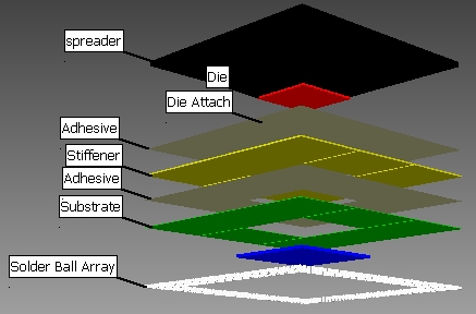
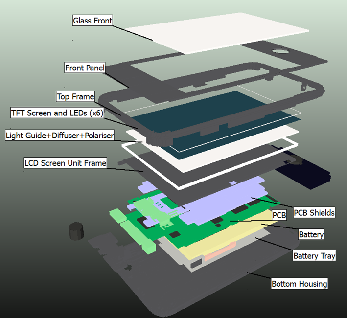 As such, a typical FloTHERM model will contain parts (with associated physical and behavioural parameters) such as: die, die attach, lead frame, die pad, substrate, boned wires, encapsulant, lid, solder ball, signal layer, power plane, ground plane, dielectric layers, pads, electrical vias, thermal vias, connectors, capacitors, LEDs, RF cans, EM shields, potting compound, thermal interface greases/pads/tape, heatsinks, fan-sinks, fans, blowers, heat pipes, thermo-electric coolers, batteries, cables, vents, fan trays, enclosures, chassis, nut and bolts. To name but a few.
When making predictions about operating temperatures using FloTHERM, the thermal engineer must be sure that their model of the proposed product is accurate to the extent where the resulting accuracy of the simulation will be useful. This involves inspecting the model in various ways, often, throughout the model building and results inspection process. Sure, graphical and node tree views of the model are standard. In FloTHERM V10 we have added an additional view of the model and the data that used to define it.
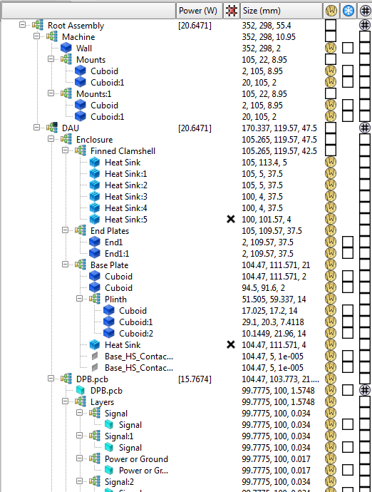 Integrated summary columns can be invoked to show a tabular type view of the model, linked to the node tree view. Columns will show, per part, what attribute is attached (name tool tipped on mouse over), size, power, cumulative power for assemblies and whether any face of that object is de-keypointed due to use of minimum cell size grid constraint.
The summary columns can be shown/hidden using the “i” key shortcut. By providing a quick view of the model input, without having to navigate to the tabs that are used to enter or set that data, the user can make the frequent inspections necessary to assure that the model has all the required settings so that they can get back to doing battle with the heat and not waste unnecessary time sharpening their software sword.
30th June 2014, Hampton Court.