Top 10 FloTHERM V10 Features – #3: FEA Interfacing
Temperature has always been, and will continue to be, a good enough leading indicator of product reliability. As a parameter it is easy to specify a maximum rating value and relatively easy to measure. However it is not temperature itself that directly causes product failure, more often than not it is some kind of mechanical fracture or deformation that itself is fuelled by thermo-mechanical effects. Differences in temperature and differences in material properties cause objects to bend, deform and possibly break. When applied to electrical circuits any break in that circuit is catastrophic in that, to put it simply, the product stops working.
Einstein famously once said that “Everything should be made as simple as possible, but not simpler”. Industrial processes tend naturally to gravitate towards this as well. Simplicity is more robust and cheaper. Humans also, whilst not inherently lazy, are programmed not to expend energy unnecessarily. It is no surprise that temperature has proved such a useful metric to gauge electronic product reliability, why go any further? Looking at thermo-mechanical behaviour will provide a more explicit understanding of the actual physics of failure. Solder joint fracture is by far the most common method of failure and whilst bulk temperature prediction may indicate probability of failure, detailed stress/strain prediction will indicate exactly where and under what conditions that failure will occur.
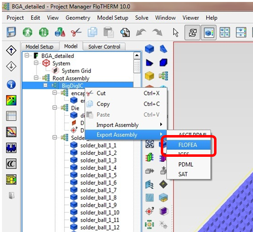 We have not incorporated a thermo-mechanical simulation capability in FloTHERM V10, instead we have enabled FloTHERM 3D temperature predictions to be exported for subsequent import into existing FEA tools. This export capability is straightforward and requires no additional license. Simply select an assembly in a solved project, RMB pop-up and Export Assembly to ‘FLOFEA’. A file will be written that contains temperature values for all solid cells that reside in the selected assembly, together with information about cell size and location.
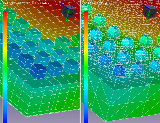
An FEA geometry and mesh is likely to differ from that used for thermal simulation. Thermal behaviour allows for certain simplifying approaches to be adopted for thermal simulation that are invalid for a mechanical simulation. Solder ball modelling being a case in point. From a thermal perspective so long as the thermal resistance of the ball, in the direction of heat flow, is preserved, the ball can be represented as a far more mesh efficient cuboidal shape. Not appropriate for mechanical simulation, especially considering it’s the stress levels in the solder ball that is the key output to be simulated and those values are geometry dependent.
 The FLOFEA file has been written so as to be importable into a 3rd party interpolation tool, namely MpCCI FSIMapper from Fraunhofer SCAI. MpCCI is a well established and highly regarded set of tools to enable CAE interfacing. An existing FEA mesh is imported into FSIMapper, as is the FLOFEA file, whereupon an intelligent interpolation is performed, mapping the FloTHERM temperatures onto the FEA mesh, the interpolation algorithms accommodating for differences in the geometry definition between the two model types. The FEA mesh and interpolated temperatures is then written out and can be set as thermal load boundary conditions in Ansys Mechanical or Abaqus.
For more information either contact Fraunhofer SCAI directly or contact your local FloTHERM account manager.
3rd June 2014, Ross-onWye


