Thermal Design Perfection Starts with the use of FloTHERM PACK
‘Plagiarism saves time’ as can be seen in the title of this blog, a nod to Tom Hausherr’s excellent blog series, particularly Part 15 that focuses on QFNs. Whereas the internal construction of a package is of little interest when defining CAD library symbols, from a thermal simulation perspective they are absolutely critical. FloTHERM PACK can be seen as a ‘pre-processor’ for FloTHERM, enabling the specification and generation of thermal models to be used in full 3D FloTHERM simulations. Supporting the parametric definition of a wide range of package styles, it can drastically reduce the time required to build an IC package thermal representation (not as much as getting a validated one from your supplier but that’s another story).
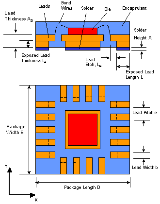 Numerical generation of an accurate thermal model representation of an IC package requires the package geometry and materials to be known a-priori. To simulate a temperature rise of a die over ambient temperature all the thermal resistances the heat experiences as it passes from the die through the die attach, pad, leadframe, PCB, chassis etc. need to be considered. For a QFN (and all other FloTHERM PACK supported package styles) this is done via a few choice parameters shown in the adjacent figures.
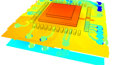
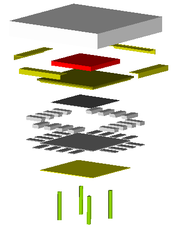 Once entered then either a geometrically ‘detailed’ model can be created or a CTM (compact thermal model, kind of a thermal SPICE model). The detailed model with have 3D geometric items representing each part of the package. Once you have that your simulations will provide a complete overview of the heat loss paths and resulting temperature gradients.
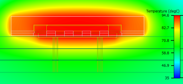
The least a thermal simulation will do is to indicate if the junction temperature of a package exceeds the maximum rated value. An observatory approach to thermal verification. A simulation was conducted of this QFN sitting on a 4 layer board with the thermal vias connected to the ground plane and the entire board edge cooled. Power dissipation = 1W, ambient temperature = 35degC.
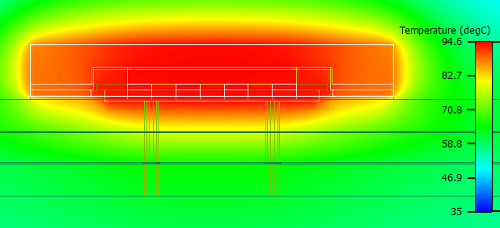
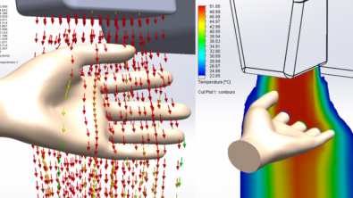
The package and vias are defined to facilitate the conduction of heat down to the internal ground plane where the heat can be efficiently removed (i.e. lots of Watts shifted with little temperature rise penalty). Examining the heat flux budget you can quantify that, in this case, the vias take about 98% of the heat. Graphically you can show this by animating the heat flux field, introducing heat flux ‘particles’ at the die:
The particles are coloured by our new Bottleneck (BN) parameter, indicating where the heat experiences thermal bottlenecks characterised by a lot of heat flow AND difficulty in heat flow. Check out this Bottleneck webinar for more details! In this case the bottlenecking effects of the vias and ground plane far outweigh any bottlenecks inside the package. So, if you’re going to do anything to lessen the temperatures then do it in the board, not in the package (though of course beyond package selection, who has the freedom to do both?).
Be it LP Wizard, FloTHERM, Expedition PCB or HyperLynx; the Board Systems Division in Mentor is the market leading one stop shop for all your PCB design needs.
April 8th 2011, Ross-on-Wye