Producing a high-quality 3D mesh in less time

Editor’s note: This article is part of a series of articles written by David Haag of Haag Enterprises, an advanced digital engineering shop specialized in delivering product development and industrial equipment and automation services. If you like this article, come back to the Simcenter Blog in August for the next article in the series.
You’ve heard the adage, garbage in = garbage out. Nothing could be truer than sending a bad mesh to the FEA solver. Poor element quality yields an inaccurate math model and depending on the quantity/location, it can adversely affect your results.
In the latest release of Simcenter Femap 2021.2, the new Automesh Bodies command can produce a high quality mesh quickly and without the traditional CAD geometry prep.
Traditional Solid Meshing Workflow
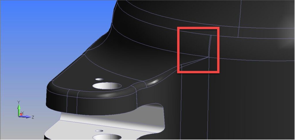
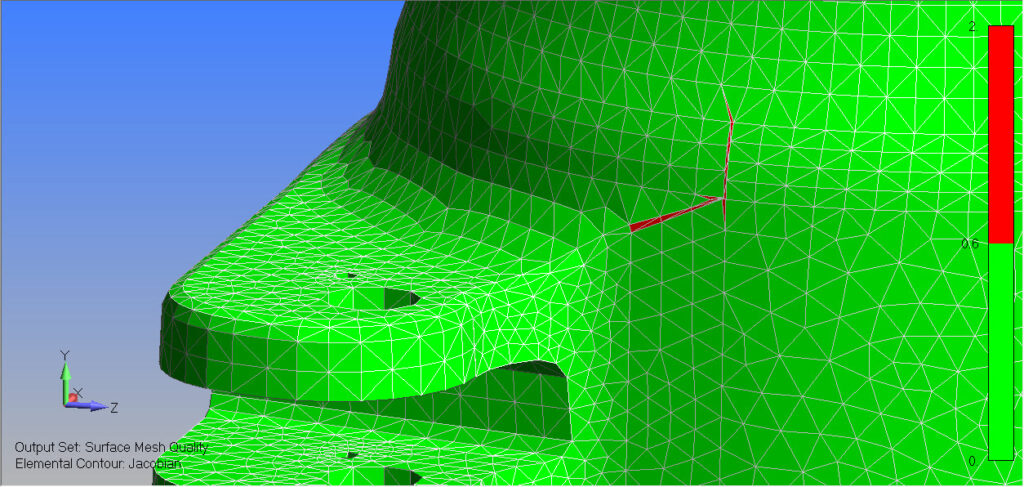
For complex 3D models, the surfaces quite often contain split faces that are a resultant of blend intersections and/or curves that have multiple small segments, as seen in Figure 1. The mesher will locate the element nodes on this geometry, which typically produces distorted elements and can be found using the Mesh Quality tool. By default, the red elements equate to a Jacobian value of 0.6 or higher, as seen in Figure 2. Simcenter Femap has a robust toolbox for fixing these issues; however, it does involve more upfront time and the goal is to produce an accurate mesh as quickly as possible, leaving more time for solving, experimenting, and optimization.
The New Automesh Bodies Workflow
Unlike the traditional solid meshing workflow, the Automesh Bodies command imposes fewer restrictions when meshing sheet solids, solids, and general bodies. Users have the option to ignore points, curves, and other mesh sizing specified on geometry, which creates a higher quality mesh, as opposed to element shape bias from curves and points in the CAD model.
At first, this might sound like the user has less control; however, there are options that allow specific geometry to be selected, which forces the elements to behave like that of traditional meshing methods. Since this command was just released to the public, it is new for me as well, so let’s experiment with the options to gain some understanding of how it works with a solid elements example.
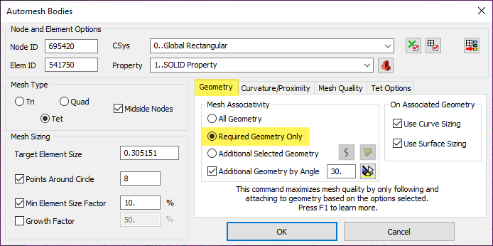
By default, Simcenter Femap calculates a Target Element Size and some predefined settings for curvature refinement, as seen in Figure 3.
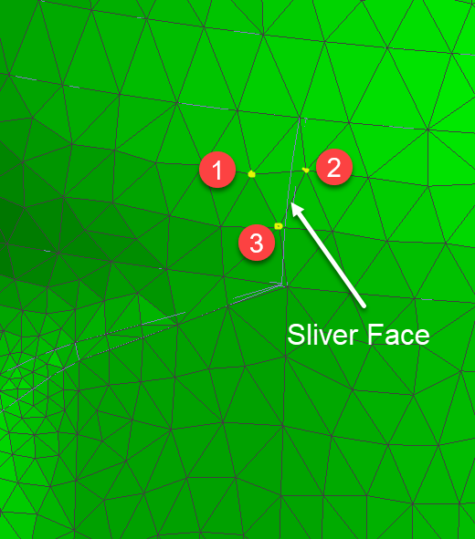
To show the power of simply using the default options, Figure 4 shows the same solid meshed with the Automesh bodies command, which produced an exceptional mesh quality. Comparing Figure 2 and 4, notice how nodes 1, 2, and 3 no longer lie on the sliver face.
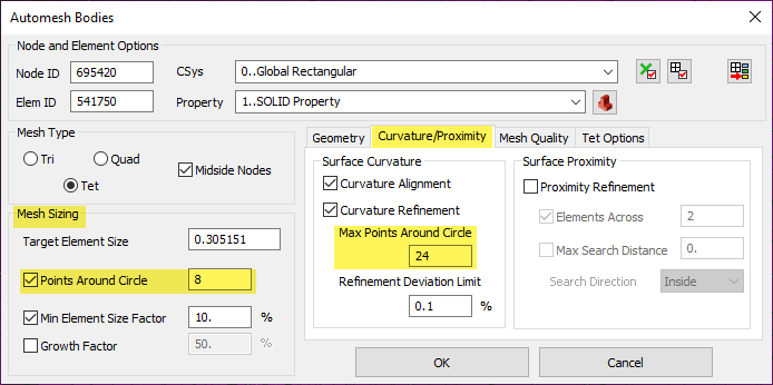
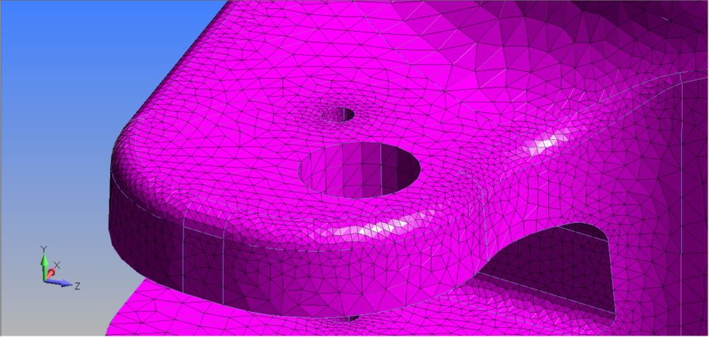
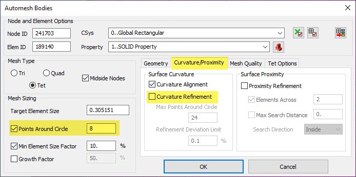
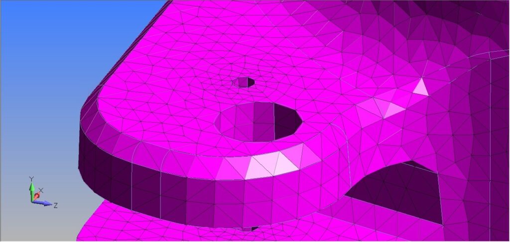
By using the Curvature/Proximity tab in combination with the Mesh Sizing option, we have fine tune control over the mesh sizing around holes and along curved faces. If we compare the results between Figure 5 and 6, we see the difference in mesh refinement along the curved faces and around the holes.
Summary
The new Automesh Bodies command empowers the engineer with a meshing technology that produces a high-fidelity mesh in far less time. No longer must we sigh after importing CAD geometry and seeing a mess of tiny faces and slivers. Instead, we can now smile knowing we have this powerful additional tool in our FEA toolbox within Simcenter Femap. I hope this new command yields increased productivity gains for you. And if you want to see a quick overview, check out my live demo video below.
And as mentioned at the beginning, if you liked this article, please come back to the Simcenter Blog next month for my third article in the “Machine Frame Digital Simulation” series.


