From CAD to CAE: Bridging the simulation gap with the geometry preprocessor
In the fast-paced world of product development, engineers constantly strive for innovation, efficiency, and accuracy. Yet one persistent bottleneck continues to slow the journey from design (CAD) to high-fidelity simulation (CAE): geometry preparation.
It is a question familiar to many CAD and simulation engineers: Why do we need a dedicated simulation geometry preprocessor when powerful CAD systems already exist?
The answer lies in the unique demands of simulation. Meshing algorithms, the foundation of accurate simulations, require geometry that is not only visually correct but also clean, robust, and watertight. Sliver faces, unnecessary features, and small gaps can compromise mesh quality and ultimately affect simulation accuracy. Equally important is the ability to parameterize imported geometry, enabling rapid design exploration, iteration, and optimization.
The qualities of a true geometry preprocessor
A simulation geometry preprocessor is far more than a CAD viewer or repair tool. It serves as the critical bridge between design and simulation, transforming engineering data into simulation-ready models while preserving design intent. To achieve this, it must excel in five key areas:
1. Seamless CAD and PLM connectivity
A geometry preprocessor should import data from a wide range of CAD and PLM systems while preserving assembly hierarchies, part instances, metadata, and design information. For complex products such as automobiles, aircrafts, ships, or railway systems, maintaining this digital continuity is essential for efficient simulation workflows.
2. Simulation-focused geometry preparation
Simulation demands geometry that is clean, robust, and watertight. A dedicated geometry preprocessor must automatically remove unnecessary features such as logos, holes, sliver faces, and small entities, while repairing topology issues and closing gaps to create simulation-ready models for reliable mesh generation.
3. Geometry creation, modification and design exploration
Engineers must be able to rapidly evaluate design alternatives without repeatedly returning to the original CAD environment. A comprehensive geometry preprocessor should provide a full suite of modeling tools, including extrude, revolve, loft, sweep, synchronous modeling, and freeform modeling. Combined with parameterization capabilities, these tools enable efficient geometry creation, modification, optimization, and what-if studies directly within the simulation workflow.
4. Change management through seamless re-import
Design changes are inevitable throughout the product development cycle. A true geometry preprocessor should support seamless re-import of updated CAD data while automatically preserving existing geometry operations, parameters, and simulation preparation work. This capability eliminates repetitive preprocessing effort and significantly reduces turnaround time between design revisions and simulation.
5. Advanced engineering and automation capabilities
Beyond geometry preparation, a powerful preprocessor provides specialized tools for CFD and FEA workflows, supports both B-Rep and convergent modeling, enables intelligent geometry queries, and offers scripting capabilities for workflow automation. These capabilities allow engineers to efficiently handle applications ranging from electronics and batteries to turbines, engines, aircrafts, and ships.
Simcenter STAR-CCM+’s geometry preprocessor: The ultimate bridge
Among the solutions available today, Simcenter STAR-CCM+ geometry preprocessor stands out by combining these capabilities within a single simulation-focused environment, acting as a seamless bridge between CAD systems and CAE workflows.
The seamless CAD-to-CAE integration: A Siemens success story
The discussion around the optimized pipeline within the Siemens Digital Industries Software Ecosystem highlights a groundbreaking solution for seamless CAD-to-CAE integration, accelerating digital engineering and enhancing product lifecycle efficiency.
The core business bottleneck often arises from the friction experienced by engineering teams when extracting complex models from secure PLM systems into simulation environments. Manual exports lead to a loss of critical data provenance, degraded structural constraints, and stripped-away parametric engineering intelligence, significantly extending verification loops and increasing costs.
The enterprise-integrated solution involves an automated, managed data workflow starting from Designcenter NX, dynamically governed through Teamcenter using PLMXML schemas and the Designcenter NX Adaptor. This ensures that structured assets are passed directly into the geometry preprocessor and onto Simcenter STAR-CCM+, creating a fully traceable architecture that preserves design structure, assemblies, metadata, and unique geometry.
Key operational differentiators:
- Secure, trackable PLM data flows: Minimizing raw geometry exports and maintaining data integrity.
- Fully associative assembly hierarchy
- Automated geometry cleaning tools: Including defeaturing, logo/irregular hole removal and small entities removal tools.
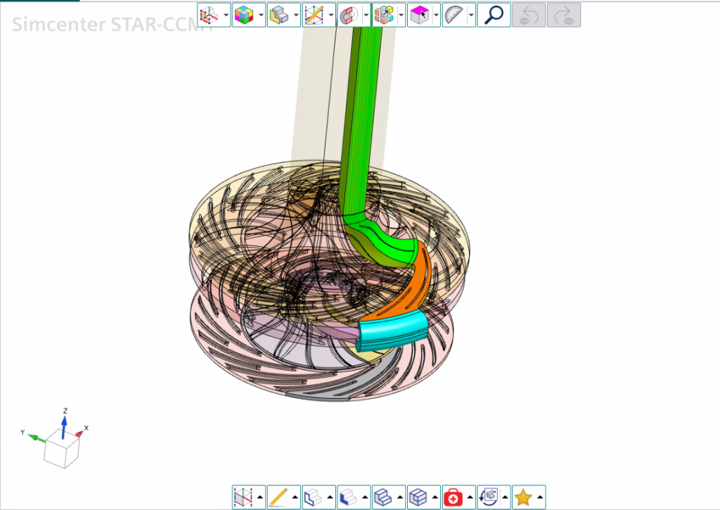
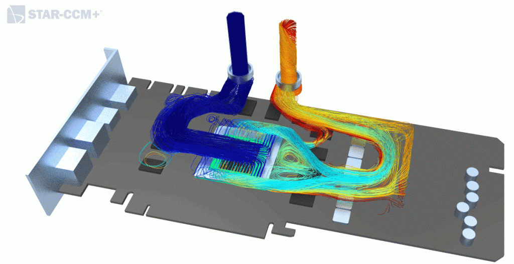
- Specialized parametric tools: Covering freeform and turbomachinery, battery, IC engine fields, with capabilities to extract internal/external fluid volumes and track contacts.
Core technical pillars of the geometry preprocessor
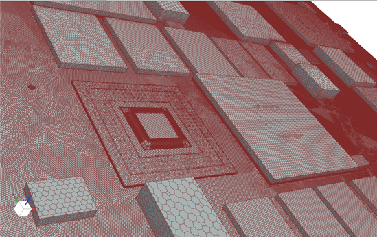
Geometry preprocessor seamlessly transforms PLM-managed structures into simulation-ready computational domains, built on several core technical pillars:
- Full assembly support: Extracts and displays the complete hierarchical tree structure directly from Teamcenter via PLMXML metadata, retaining custom names, part strings, and tracking attributes. Allows users to apply assembly constraints.
- Advanced repair tools: Scans, identifies, and resolves non-manifold structural design anomalies, building watertight computational boundary volumes required for mesh generation. This includes:
- Defeaturing: Automatic removal of secondary blends, chamfers, and rounds.
- Logo removal: Rapid stripping of corporate branding text and part stamps.
- Irregular hole removal: Patching complex unlinked structural cutouts.
- Bridge volume: Closing clearance gaps between parts.
- Repair-Cad: Converts invalid geometry into simulation-ready geometry.
- Advanced preprocessing specializations: Leveraging tailored functional sandboxes to fast-track targeted physics and geometric setups, such as:
- Freeform modeling tools: Integrating a direct, highly adaptive modeling engine within the simulation preprocessing canvas, empowering analysts to make localized adjustments without reverting to standard CAD workflows. This includes direct surface morphing, aerodynamic optimization loops, and interactive shaping.
- Dedicated turbine tools: For blade profiles, passages, hub, and shroud trimming.
- Facet/Mesh to B-REP: Converts convergent model into editable B-rep geometry.
- Search tools and query mechanism
- Various query mechanisms to identify topological entities
- Usage of queries in individual Features
- Contact browser: Provides a quick way to verify face-to-face contacts before meshing.
Case study: Parametric modeling and geometry modification using freeform tools
The Freeform tool in geometry preprocessor provides a powerful way to modify and parameterize imported geometry. By controlling edge boundary conditions, engineers can rapidly create and evaluate multiple design variations without returning to the source CAD model.
Case study: Preparing a complex engine model for CFD Simulation
This workflow demonstrates how a complex engine assembly can be transformed from production CAD data into a simulation-ready computational domain. Using advanced repair, defeaturing, topology cleanup, and fluid volume extraction tools, engineers can rapidly eliminate geometric issues, generate watertight fluid regions, and accelerate the transition from design data to CFD analysis without returning to the source CAD model. The example highlights how a dedicated geometry preprocessor accelerates simulation setup while preserving design intent.
Quantifiable business Impact
The optimized integration pipeline yields significant business benefits:
- Reduced geometry preparation time: Automated defeaturing, feature stamp/plug cleaning, and irregular hole cleaning can shrink preprocessing time from days to mere hours.
- Improved design iteration rate: Parametric variants cycle quickly from Designcenter NX/Teamcenter via the Designcenter NX Adaptor directly into active simulation loops without resetting parameters.
- 100% data provenance & structure integrity: Automated Teamcenter managed PLMXML + Designcenter NX Adaptor pipeline flow replaces traditional neutral file exports that cause history and hierarchy loss.
- Lightweight models & fast file load ins: Smart object instancing coupled with metadata transfer addresses challenges of unmanaged component duplications in large assemblies.
In an era where simulation-driven engineering is essential for product innovation, the geometry preprocessor has become a strategic enabler rather than just a preprocessing tool. By bridging the gap between CAD and CAE, Simcenter STAR-CCM+ geometry preprocessor helps engineers spend less time preparing geometry and more time generating insights that drive better products.