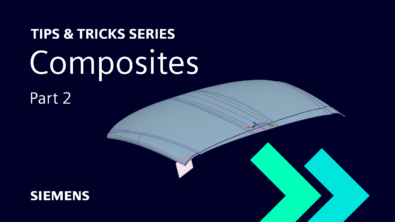
NX Composites: Part Two | NX Tips and Tricks
It’s time for another exciting episode of the NX™ software tips and tricks series! We’re going deeper into the amazing features of the December 2022 release of NX. Thanks to our continuous release cycle, we’re always adding new functionality to NX based on your suggestions and feedback.
Our previous entry into the series investigated NX Join. If you missed it, check the video here.
Now, onto this week’s episode.
An introduction
On this week’s episode, we are going to be circling back to the second part of composites. To review what was covered in part one, let’s list the main points:
- Define the layup surface
- Define the composite region
- Defining and selecting the laminate
- Creating a composite material
- Performing a producibility simulation
- Examining the results
Here’s some exciting news – we are going to build upon these concepts today for a full landscape view on Composites within NX.
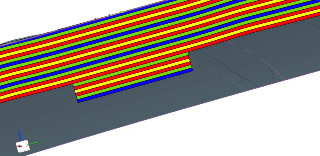
Change line widths and orientation colors to distinguish layers
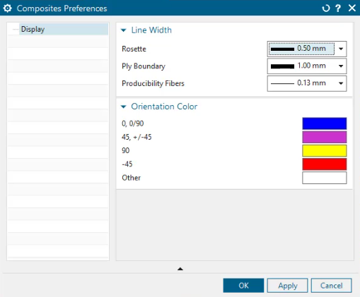
When working with composite parts, it is important to know the scale you are working with. For this example, let’s say that our scale is set to one. Now, our displayed cross section will be displayed with a scale of one. If we go to view our cross section and decide that the layers are a bit thin, an easy solution is to change the ply scale to bring the layers to life.
Now that our layers are viewable, we can see the colors of each ply layer. Within NX, we can customize these layers by accessing composite preferences within the menu. If there is a certain layer that you are focused on, this would be a great way to distinguish it with a color that pops.
Top Tip: Use the show and hide command, which can be quickly accessed with Control W, to show or hide any features that are necessary.
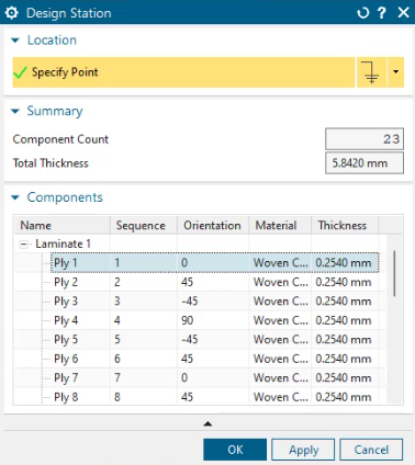
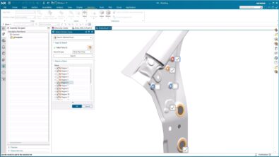
Design station analysis
The next piece of functionality to look at is the design station. Here, we can select a point on the part to analyze the direction. The layup is indicated by the arrow from the point, and we can view information like the number of ply layers, thickness at that point, and other information about each layer. When selecting a ply layer, that region will become highlighted for ease of use. Once the design station is complete, click on the composite navigator to select what you would like additional information on.
Fixing invalid ply layers
After our analysis, we can see if the model was rolled back, or the composite region was affected. If a reference region is deleted, the ply layers will need to be reassigned to a region to become valid again.
To conclude
We hope that you have learned something new about composites during this week’s tips and tricks series. To recap what we have covered today, we have learned about:
- Distinguishing layers with colors and line widths
- Running a design station analysis
- Fixing invalid ply layers and reassigning them
To find a full suite of NX tips and tricks, click the first link at the bottom!
NX Composites: Part Two | NX Tips and Tricks YouTube Video