Interpart Modeling: Part One | NX Tips and Tricks
Striving to help our customers get the most out of NX™ software is a core value around here at Siemens. When our customers can utilize the comprehensive digital twin to create new and exciting designs, that means that we all have succeeded at the end of the day.
In this installment of the Tips and Tricks series, we will look at how using interpart modeling can enable quick and efficient changes in assemblies. These tips are a guide to helping you discover new functionality that you may not have seen or used in the past. If you use interpart modeling, stay tuned for Part Two coming soon.
Create non-associative links for interpart modeling
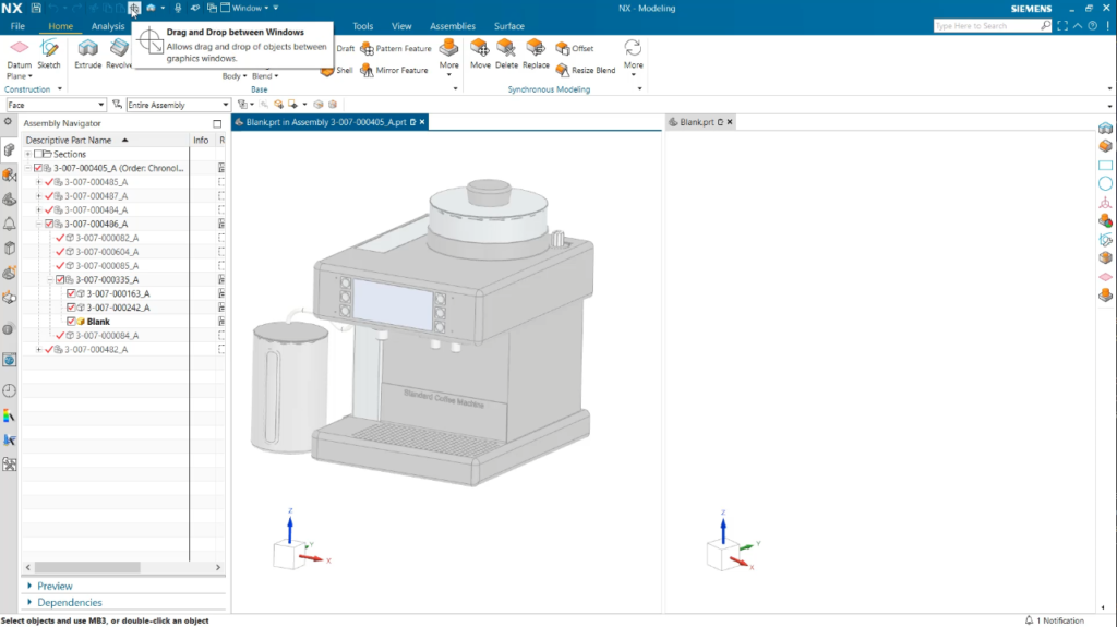
Managing all of your design data and geometry can be a large task, especially when you are working with multiple parts. By creating non-associative links while using drag-and-drop geometry, this will enable new capabilities to move select faces seamlessly between windows. By nominating one window and part within your assembly to be your active part, all changes in addition to this will appear on the same level of the assembly. This allows for geometry from one part to be selected and used to create geometry in a new window.
Top Tip: Utilize non-associative links to simplify clutter on larger assemblies. Changes made in your active workspace will also be applied to geometry in other windows.
Use associative linking for interpart modeling
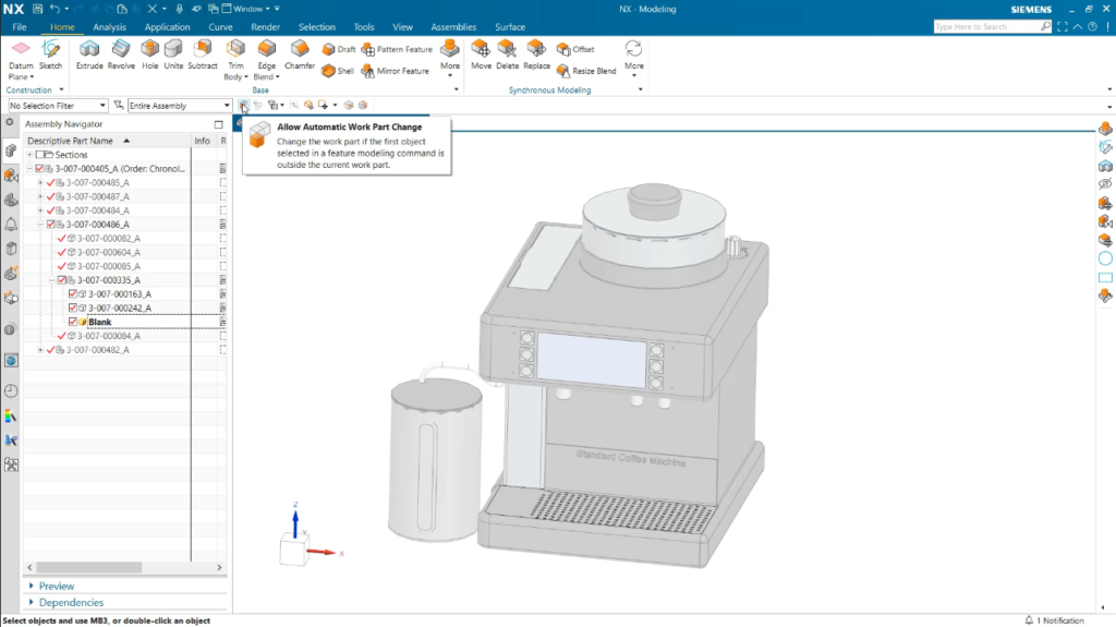
The difference between using associative and non-associative linking is multiple windows versus a single window. By utilizing associative interpart geometry, you can make changes to a feature or curve and the new geometry is adapted in your current working window.
Top Tip: Select automatic work part changes to make changes from outside your active part. Deselect automatic work part changes to select features in geometry from other parts without changing your active work part.
Valuing the automatic timestamp
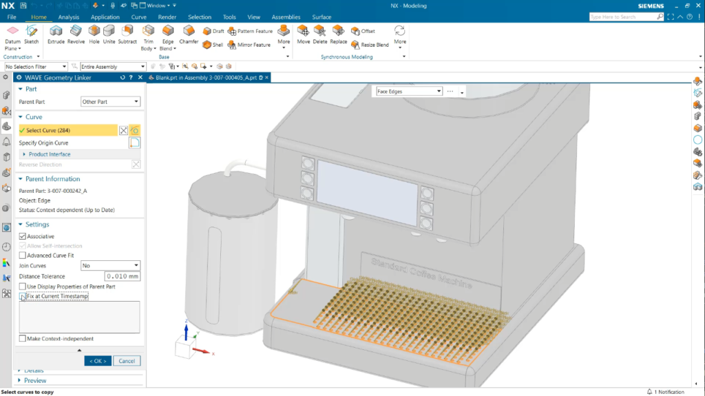
The final tip to cover today highlights the functionality of the create interpart link tool command. This command also allows for geometry to be linked to parts outside of the active work part. While this may sound like non-associating linking, the differentiating factor here is the automatic timestamp that is implemented within NX. This was created to prevent unintentional changes to your active part, when editing previous parts. To carry out the alterations made to previous parts, enter the part navigator and uncheck the timestamp box. You will then automatically see the changes made to match.
Conclusion
We hope that these tips and tricks have provided new and relevant information that you can incorporate into your own NX workflow. There are more tips and tricks to come each week, so stay tuned in to the NX Design Blog!
NX | Tips and Tricks | Interpart Modeling: Part One | YouTube Video
Take me to the NX Design blog