Confused by “Scope of Verification” in ISO 26262?

by Chuck Battikha, Solutions Architect for Functional Safety, Siemens EDA Verification Consulting
Do you know what you’ll need to verify to meet ISO 26262 requirements? It’s not surprising if your answer is ‘no’, as ISO 26262 provides all of three and half pages (!) to the definition of Verification (Part 8 Clause 9). It also references this clause from six places within the standard: from verification of requirements to verification of results for generated metrics (SPFM, LFM, and PMHF) to the overall verification of the design, and verification of the integrated design. In short, the clause is more of a planning framework. It specifies just enough so that consumers of the required verification plans, specifications, and results might have enough information to determine if the verification was sufficiently planned and executed.
So how do you determine what ISO 26262 requires for verification? Let’s start with 5:7.4.4 in the actual standard, Verification of hardware design. Here, the standard refers to the verification clause, but we already know that this section is, really, about bookkeeping. In 5:7.4.4, it calls out methods that include simulation, but it doesn’t really call out what here either. The what is based on asking and answering the question, will my design achieve functional safety?
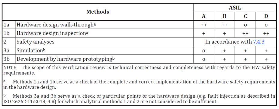
There is additional information, in Part 11, Guidelines on application of ISO 26262 to semiconductors (specifically, Table 31 and Table 41 (typical IC developers). In these tables, the standard makes it clear that the breadth and depth of systematic failures (and thus what is intended by verification specified in 5:7.4.4) is inclusive of the following elements, depending on design specifics:
- Functional Verification (Digital, Analog, Mixed Signal)
- Timing
- Physical design including synthesis
- Power
- Performance
- Integration
- DFT
- Lab / Validation
- Etc.
So, by comparing the requirements of the verification clause with these needs, it becomes clear that simply calling out just your functional verification test cases and their pass/fail status is going to come up short when measured against potential systematic failures in your design. ISO 26262 is looking for projects to plan and capture all the information that could lead to systematic failures. This includes:
- Functional Test Case Status
- Functional Coverage Results
- Code Coverage Results
- Static Timing Results
- And a long list…
Yet, what all projects should strive to accomplish when considering meeting ISO 26262 requirements is to be efficient in the creation and maintenance of the ISO work products. As soon as work is ‘cut and pasted’ from one area of a project (example: regression results) to the ISO 26262 work products, both the project and the ability to demonstrate a safe design have been impacted, both now and for the future.
Building the Work Product
Instead, view the requirements of the verification clause as a refinement of what well-managed projects should already being doing: planning the work and ensuring that the work was done completely and accurately as per the plan and that results have captured. Thus, the work products defined in ISO 26262 can be viewed as:
- Verification Plans: A high level set of documents that can organize the verification efforts into different domains and set pass/fail criteria, as needed.
- Verification Specification: A set of documents that indicate how the plans are to be implemented.
- Verification Report: Capturing or referencing the results called out by the testing requirements in the specifications. This also includes any waivers and their justifications. For example: technical explanations as to why 100% code coverage is not achievable.
Graphically, the organization of these documents is shown in Figure 2.
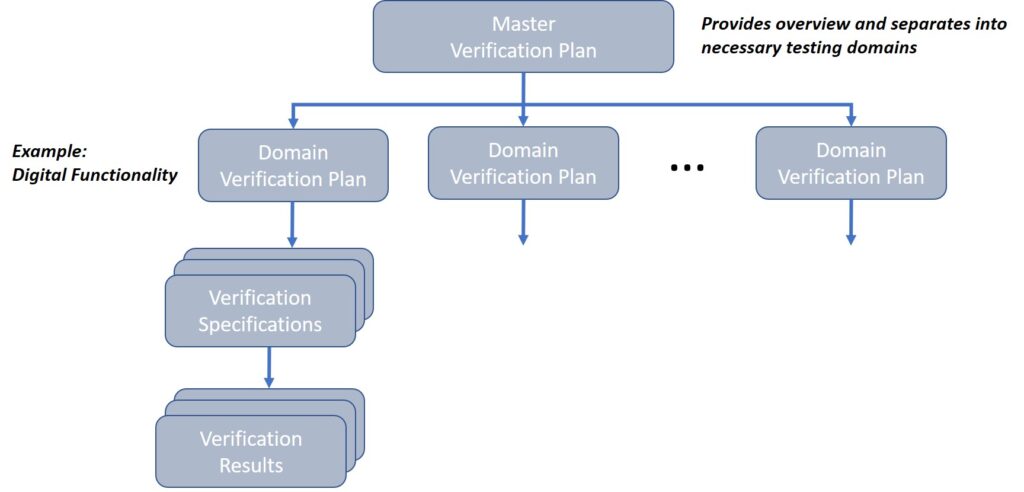
Partitioning the verification plans and specifications into distinct domains improves:
- Re-usability of information
- Technical Focus
- Reviewability
The verification specifications are then written to match the scope of their specific domain. For example, Digital Functionality would likely need to call out the following implementation details:
- Random Stimulus
- Directed Stimulus
- Functional Coverage
- Predictors, Scoreboards, and other UVM structures
- Reporting through regressions and coverage results
Meanwhile, Timing Verification would likely include:
- CDC Testing
- STA Process
- Dynamic Timing tests of specialized hardware
- Reporting through checklists of steps and reviews of generated reports
In practice, these Verification Specifications can (and should) be written very differently. There is, therefore, no need to “crowbar” all of your disparate verification documents into the same style.
Building your Verification Documents
Other key points to consider when building and collecting your verification documentation:
- Avoid cutting and pasting large amounts of technical data into your verification documents. Use as much of what your project creates as possible. Reference these documents from a master verification plan or from your Safety Case.
- Remember that these documents are also governed by the change management, documentation and configuration plans required by ISO 26262 (8:8, 8:10, 8:7, respectively).
- Requirements (or, at the very least, your safety related requirements) need to trace through these documents bi-directionally. This means that a Hardware Safety Requirement (HSR) or Software Safety Requirement (SSR) should trace both to a testing/checking mechanism and to a result (pass/fail).
- Results can be shown in multiple forms: test case(s) being run, a checklist driven review being completed and documented, a tool being executed and the result verified, etc.
- Bi-directional traceability means each requirement can be shown to be verified in the verification tasks, and each step in the verification tasks can be shown to be supporting one or more requirements.
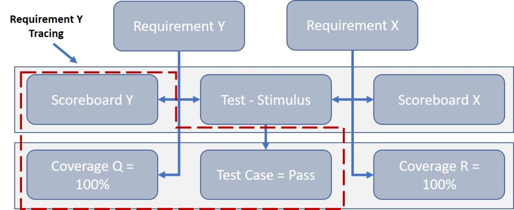
- Requirements can have multiple paths to results. This is especially true in constrained random testing where testing of a requirement might trace to a test (stimulus) + Scoreboard + Assertion + Coverage. Likewise, a result such as a functional coverage coverpoint, might be linked back to multiple requirements. This magnifies the importance of bi-directional requirements traceability and the use of applications (such as Siemens Polarion) for this function becomes critical. See Figure 3 for an example.
- Results for complex IP, IC, and SoC projects are typically created by EDA Tools (Example: Siemens EDA Questa Verification Run Manager): reference these outputs from the Verification Report document. For example, if you have a regression of a hundred test cases, do not cut paste the VRM output into the Report: reference, instead, the tool output that should be checked into source control (per configuration management plan) and summarize the results in the Report.
- Example: “Regressions were run on <date> by <engineer> with results located <path> indicating that all tests passed with coverage of 100% as shown in coverage report located <path>…”
- Of course, these referenced reports should be managed like all work product documents.
We hope that this demystifies some of the language around verification within the ISO 26262 standard.
If you require deeper guidance on the intricacies of verification for ISO 26262, Siemens EDA offers a wealth of experience in collaborating with teams to smooth the path toward compliance. Contact your Siemens EDA representative or drop us a line at SiemensEDAServices.sisw@siemens.com