Student Spotlight: Solid Edge Design Contest Winners
(This article was originally posted in the Solid Edge Blog and was written by @AmyReyes1)
It’s amazing to see what our students are capable of, and the level of skill they have developed often early in their education. Frankly, I am blown away by some of the designs and the attention to detail that makes these models so realistic. Never is this more apparent than when perusing the entries in the Student Design Contest.
If you aren’t familiar, the Student Design Contest gives students the opportunity to highlight their work and receive global recognition. The contest is hosted year-round with prizes and certificates awarded monthly to the top design submitted in that time period. Images are judged by industry professionals based on the dramatic impact and aesthetics of each image, complexity and innovation, as well as quality. Of course, designs must be created using Siemens PLM Software products.
This month, we’d like to highlight a few of our past winners from April and May who used Solid Edge to design their winning models.
April 2018 Winner – V8 Engine
Gareth Montgomery, a senior student at Ulster University in North Ireland, designed this fully functional V8 engine for his CAD module course this semester. He chose to design an engine because he is a keen car enthusiast who is interested in motor technologies, and he would love to enter a career that involves automotive design.
His model exhibits the type of engine that would be used in a high performance road car before direct injection was introduced. The camshafts are belt driven through the crankshaft like a real life engine, which in turn rockers the valves open and closed in certain time delays. His design includes an intake manifold and exhaust manifold, both with a smooth constant form to produce good airflow properties. All components of this engine were designed using Solid Edge through a variety of commands such as 3D features, variables tables, Xpress Route and surface modeling. KeyShot was then used to experiment with different lighting, environments and materials to render high-quality images of the final product.


Exceptional work, Gareth!
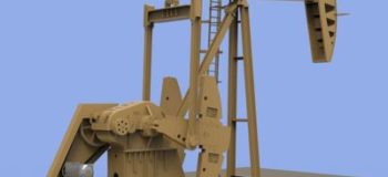
May 2018 Winner – Maximizer II Oil Rig
Joseph Barragree, a sophomore at the University of Alabama in Huntsville, designed this oil rig for a CAD class in his program. He chose to design an oil rig because they are common in his home state of Kansas. This gave him the chance to model something that is both familiar and complex. His assembly is based closely on diagrams he found of the Weatherford Maximizer II unit, and he used available dimensions for their 912-365-168 model. Joseph is currently studying to be a mechanical engineer.
He used the ordered environment in Solid Edge to make all parts and assemblies in his design. There are 1,125 total parts in the assembly, which comprises 13 subassemblies for the bearings, two families of parts for the nuts and bolts, and 160 unique parts. One motor drives the entire assembly, transmitting the power accurately through the gears and arms across 7 axes of rotation to move over 400 parts. The motor presented some difficulty to model accurately as the diagrams lacked large amounts of information on that section. Due to time constraints that prevented him from accurately modeling a combustion engine, Joseph chose to use an electric motor, which he based off of images and videos he found online. He placed the nuts and bolts using patterns and mirrors whenever possible, though he did run into challenges with them. The nuts and bolts placed individually were fine, but those that he patterned into moving parts would often get left behind in the simulation.

The biggest challenge he encountered during the design of this project, though, was calculating the internal loop of moving parts—where the single gear shaft goes to two arms with counterweights, which then go to the longer arms leading to the equalizer beam—and also computing the movement of hundreds of moving parts. “The relationships were all placed properly,” Joseph writes. “I could use drag component with rotation setting on the motor axle to move the entire assembly, but when I tried to run the motor it failed. The only solution to this was to remove the entire set of arms and bearings on one side.” Another minor difficulty was getting evenly spaced and sized teeth for the helical gears based on the distance between gear axles. It took him quite a while to devise a method to get proper spacing, and even after revisions, there remained some imperfections.
More than 32 features of Solid Edge were employed by Joseph to create this winning design, including extrusions, rotations, lofts, sweeps, chamfers, rounds, flange and contour flange, bead, dimple, axial align—just to name a few. Joseph would recommend Solid Edge software to fellow students because it is free, user-friendly, and capable of most things a standard student would want. “Solid Edge is better than any other free CAD program I have encountered,” he said.
Very well done, Joseph!
You can participate by downloading a free copy of Solid Edge Student Edition and submitting your entry at the link here: Student Design Contest