Exploring Manufacturing Driven Design for automated DFM

Manufacturing Driven Design leverages the intelligence within your PCB Design

Intelligent Process-Driven DFM Analysis for PCB Designers Recent component shortages and distribution disruptions have exposed both the fragility of global…

PCB Design and Stencil

Stencil design considerations during library cell design

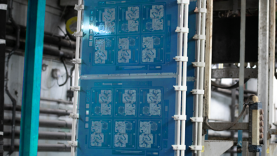
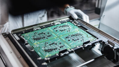
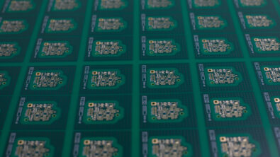
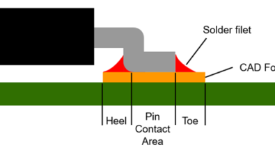
Library cell design seems to be an easy part of the entire design process, but in reality, it can be a complicated part of this process, as it involves many different aspects to consider. It should not only comply with the electrical needs, but also needs to meet manufacturing requirements. Solder paste printing is one of the manufacturing processes that may need considerations during your library cell creation. To be more straightforward, the stencil design is something need to be considered during library cell design.

pick and place machine on PCB SMT line

How to Optimize PCB Design for the SMT Assembly Process Flow

PCB (Printed Circuit Board) design layout optimization is critical for the success of SMT (Surface Mount Technology) assembly. SMT assembly involves placing surface mount components directly onto the surface of the PCB, as opposed to through-hole components, which require holes to be drilled through the PCB. SMT assembly is faster, more precise, and more cost-effective than through-hole assembly, but it requires careful design optimization to ensure a successful assembly process.

Migrating from Gerber to ODB++ CAM Compare

Gerber files have long been the industry standard for PCB design and manufacturing data. However, with the increasing complexity of modern designs, Gerber files have become less effective in conveying all the necessary data required for manufacturing. ODB++ is a newer format that was developed specifically to address the shortcomings of Gerber files. ODB++ is a comprehensive format that includes all the necessary data for manufacturing, including component placement, drill files, and manufacturing details such as the thickness of the PCB and the type of solder mask just to mention a few.

What is DFM and DFA?

DFM and DFA are relevant to almost any product be it assembling bicycles where primarily the product is mechanical components to electronic devices such as cell phones, routers, and computers which require both mechanical and electrical components. The primary focus of this blog will be PCB Design through PCB Fabrication and PCB Assembly within the electronic realm and how it relates to DFM and DFA.

What’s New in Valor NPI 2305

Valor NPI has recently been updated with version 2305. Included within are many of the revisions and feature updates for this latest version of the software

Making Parts Part of Manufacturing Driven Design

When it comes to PCB assembly level MDD, many designers have not concerned themselves with the component manufacturing Bill of Material (BOM). Designers work from a CAD library that has component libraries associated with internal part numbers (IPN) their company uses. The CAD Design Rule Checking software uses those CAD library shapes for its analysis and even, in some cases, the avoidance of where components are placed. There is nothing wrong conceptually with this mentality. However, like all things, the details matter.

detectives investigate DFM within a PCB design

The Mysterious Case of the Missing Bowties Part III

Previously… People often say ‘better late than never’, but I’ve never heard my boss say that. After much difficulty in…

The Mysterious Case of the Missing Bowties Part II

Previously… After receiving our boards and having them pass inspection I breathed a sigh of relief as this project was…