Choosing the right laminate for your PCB design
In recent years it’s become more important to choose the right material for every PCB design. In the past, there were a limited number of high-speed laminates available on the market, namely Nelco’s N4000-13 or N4000-13 SI. Today, there are hundreds of choices – so many that we risk being overwhelmed with options. A general understanding of the nature of the materials can help to mitigate this risk, and a powerful PCB library comparing the material properties can help to alleviate the possibility of analysis paralysis.
In general, with dielectric materials, every parameter that improves performance comes at a marginal increase in cost. Because of this, ensuring that you don’t overdesign within your materials is quite important. Just like buying winter tires in a climate that never sees snow adds additional unnecessary cost without increasing performance, likewise a thin board simply does not need a high Tg value, as the temperatures for the board will remain relatively low during assembly and rework. If this value is unnecessarily robust, alternate material selection can lead to an overall decrease in cost without adversely affecting performance.
All of the relevant information necessary to make detailed production decisions is readily provided by laminate manufacturers on their material datasheets. However, comprehending the meanings behind these values is not necessarily straightforward. Understanding how they are generated and what they represent can help you isolate the parameters most likely to impact performance and overall costs. Occasionally manufacturers will use different test methods to characterize properties within their laminates and while the values will represent the same material characteristics, their values will not be relative to one another. This can make it difficult to compare “apples-to-apples” in electrical properties across multiple laminate systems, constructions, and data sources to select the best laminate and dielectric materials for each application.
Breaking down the parameters of the datasheet
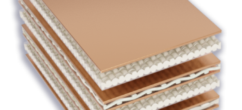
Although every manufacturer’s datasheet is different, the values they include can be divided into three categories: electrical, thermal, and mechanical.
A balanced approach to material selection involves understanding and considering more than just electrical parameters.
Electrical PCB parameters
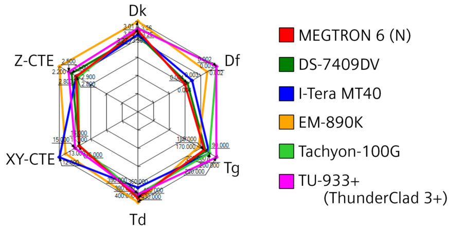
The most obvious thing to look at on a datasheet is the electrical parameters, such as the dielectric constant (Dk) and the dissipation factor (Df) also known as loss tangent (tan δ). While a lot of attention is focused on laminate Df values, it is also important to understand Dk—lower Dk allows for thinner dielectrics, reduced crosstalk, and lower board thickness, albeit typically at a slightly higher cost.
In general, lower is better for both PCB dielectric constants and dissipation factors, but it’s also more expensive. If you know where you need to be from a loss category standpoint, you can narrow down the list of possible materials and pinpoint the ones that deliver the needed performance without overdesigning and adding unnecessary costs.
Thermal PCB parameters
There are several thermal parameters associated with PCB laminates, but certainly the 3 most important are glass transition temperature (Tg), time to delamination (Td), and the coefficient of thermal expansion (CTE). Independent of the environmental temperature the board will be deployed within, these values are important because the thermal gyrations the PCB is exposed to during assembly and rework can potentially impact the life of the board itself. Design characteristics, specifically board thickness is a critical consideration, as thicker designs go through more temperature changes during fabrication. We must also keep in mind Z-directional temperature stresses are additive, meaning there are more opportunities for failure.
The European Union’s Restriction on the Use of Hazardous Substances (RoHs) directive has had an impact on thermal parameters as the lead-free solder required today has a higher melting point than tin-lead materials, and therefore temperatures during assembly or rework can reach >260°C multiple times. For thicker boards, it’s better to choose high glass-transition-temperature materials and materials with comparatively low z-CTEs. With thinner boards, manufacturers can save 25% or more on material costs by using mid-Tg materials, which can be critical in high-volume production.
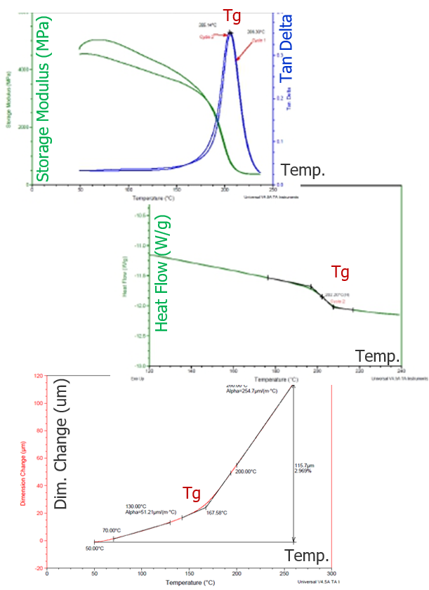
There are three ways to measure Tg and laminate vendors have not yet settled on a single method. Regardless, each method measures the same property, the material’s softening temperature, but projects these values with different numbers. You must ensure that you are comparing like methods between materials.
Dynamic Mechanical Analysis (DMA)
The best method to use is the dynamic mechanical analysis (DMA) method. It detects changes in the storage modulus and loss modulus (Tg: peak temperature of the tan delta; IPC TM-650 Method 2.4.24.2).
Differential Scanning Calorimeter (DSC)
The next best method is differential scanning calorimeter (DSC), which measures the flow of heat into or out of a sample while the sample is heated (Tg: temperature at half height of step change in heat flow; IPC TM-650 Method 2.4.25).
Thermomechanical Analysis (TMA)
The last method is thermomechanical analysis, which measures changes in the height of the sample vs. temperature (Tg: temperature where CTE changes; IPC TM-650 Method 2.4.24.24, 2.4.24.5).
Mechanical PCB parameters
Mechanical parameters are an indication of the strength of a board, including the strength of the material under various test conditions, how it absorbs moisture, and the resin’s adhesion to copper. For most mechanical parameters, the level of detail in a datasheet varies depending on the manufacturer. Some include peel strength, flexural strength, moisture absorption, thermal conductivity, Young’s modulus, and Poisson’s ratio, while others include only some of those parameters. In addition, multiple values can be listed for each parameter. However, it is important to remember that not all parameters are going to be important for every design—which ones are critical depends on the design of the board, technologies used to produce that board, and the end-use application. Adding this consideration prior to your design phase is key for complex high-speed boards with multiple layers.
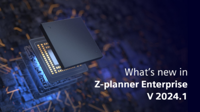
Dielectric material library
A library that contains equivalent values across all parameters is valuable when comparing laminates. Z-planner Enterprise includes a dielectric materials library that provides qualified PCB-laminate materials from 200 laminate families which can be inserted directly into the field solver for instant material comparison and qualification. Complete material information is available for each selection, including frequency-dependent Dk and Df values for thousands of core and prepreg combinations right out of the box. With Z-planner, designers can choose the right laminates for every design without the risk of over- or under-designing. Start a free trial of Z-planner Enterprise.
Learn more about how to read a laminate datasheet in the new ebook, “Stackups – The Design Within the Design” from I-Connect007, written by Bill Hargin, an expert on signal integrity, stackup design, and material selection.