DFT architectural tips: use of boundary scan chain during ATPG
DFT designers often use boundary scan chains for 1149.1 or 1149.6 interconnect tests. This video provides tips on how to use boundary scan chain as compressed chains during ATPG.
 Boundary scan insertion can be performed with the Tessent Boundary Scan tool at the RTL or gate-level, which instantiates the IO pad macros. In a recent video by Mentor’s Vidya Neerkundar, she describes the options available for boundary scan insertion and what happens during the insertion process, then also how you can use the chains during ATPG to minimize the number of test pins needed.
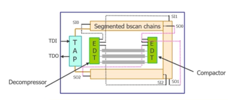
Within a chip, the boundary scan can be used as compressed or uncompressed chains to connect to compression logic on the chip. The boundary scan chains can be segmented to match the rest of the scan chains, which is better for achieving higher compression. During ATPG, on the input side, boundary scan chain can isolate the core from primary inputs. On the output side, they can tri-state the pad buffers. Using boundary scan chains in this way during ATPG helps to improve test coverage, particularly for low-pin count designs.
The Tessent platform integrates all the Tessent DFT tools into an RTL-based hierarchical flow.
If you use boundary scan, watch this brief video from Neerkundar with information and tips on boundary scan insertion.