The Electronics Cooling Metaphorical Drinking Game
There are a handful of quoted and re-quoted drivers, concepts and technologies in the electronics cooling industry. Be it a presentation, peer reviewed paper, press release, thermal design guide or webinar the same core material keeps popping up in various guises. This is by no means a bad thing. The challenges faced when cooling electronics are clear, clearly described and need to be constantly reiterated. If, when viewing such presentations, reading the articles or attending a travel budget friendly webinar you might like to partake in this electronics cooling ‘metaphorical’ drinking game to pass the time.
The following items, should they be encountered, will score the following drinking game points penalty… I’ll leave it up to you to decide how those penalty points should be paid.
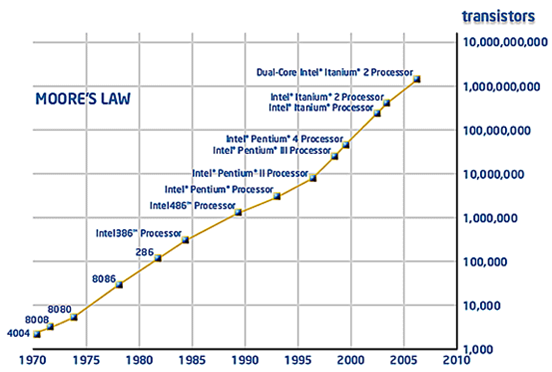 Moore’s Law. The number of transistors in an IC doubles approximately every two years. More an observation than a law though it has, until recently, stood the test of time very well. Considering that it is the thermally dissipated power of the transistors that causes the temperature rise and subsequent performance and reliability issues in electronic products, it’s not surprising that this graph is shown again and again. Very common: Penalty Points = 1
.
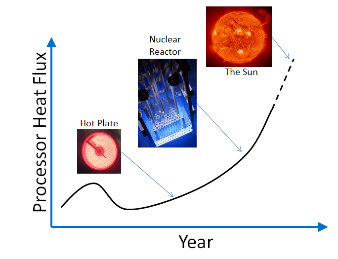 Following on from Moore’s law, the actual heat dissipation divided by the area over which it occurs is the heat flux and has been rising recently, quite dramatically. Analogies are always good, especially when you’re trying to scare the pants off an audience. Although for just a small area (of the order of a few mm^2), the heat flux values in tomorrow’s processors will be ‘as hot at the sun’ (as I’m sure the media will spin it as). Getting to be a more popular graph and it’s fun: Penalty Points = 2
.
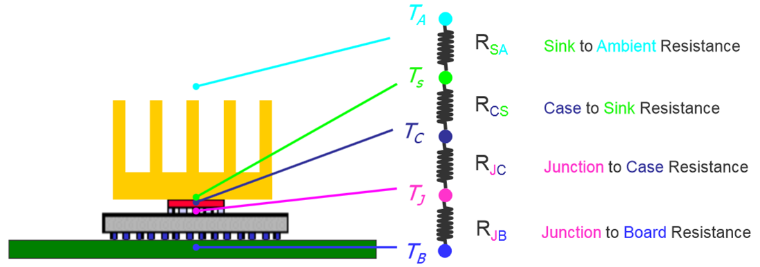 In 1822 Joseph Fourier published Théorie analytique de la chaleur in which he postulated that heat flow is proportional to the temperature difference between two points and the thermal resistance between them. Nearly 200 years later and the electronics thermal community thrives on such simple abstractions of what in reality are complex 3D heat flow patterns. Thermal resistor network descriptions of systems are as common as muck and almost twice as useful: Penalty Points = 1
.
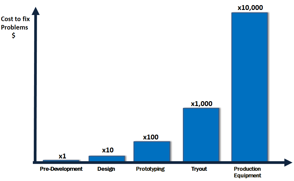 Not unique to the electronics cooling industry, the cost of fixing mistakes at various stages of the product development process is well documented. As any good sales person will be at pains to point out, anything that can front load the design process with risk identification will have a very obvious and evident return on investment. And sure, we’re no different. A graph as valuable as it is overused: Penalty Points = 1
.
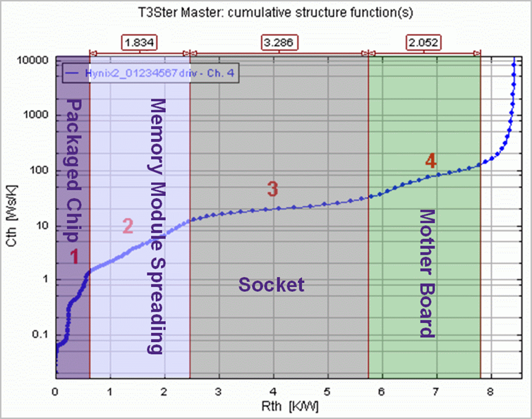 In recent years transient thermal test characterisation has become a popular non-destructive approach to investigate the physical construction of a packaged IC or discrete. A thermal equivalent to the use of X-rays, the T3Ster measurement technology is now frequently referenced in the industry. One key aspect of the value of the T3Ster approach is in the determination of a thermal ‘structure function’, a graph that indicates the thermal resistances and capacitances that exist within the package and system in which it is placed. Banded to show what parts of the graph refer to what physical part of the package/system, to understand and appreciate a structure functions is now a prerequisite for all thermal engineers: Penalty Points = 3
.
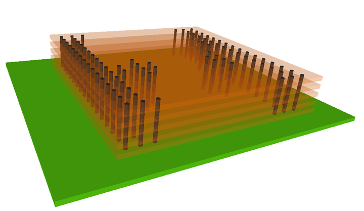 TSVs! (through silicon vias) The next big thing. Enabling die to be stacked efficiently, no need for inter-die interposers or peripheral wire bonding. From a thermal perspective you’ve just massively increased the effective heat flux. How to get that heat out is a question that has to be answered before this technology can hit the mainstream. The very high heat transfer coefficients that over-chip liquid microchannel cooling can provide seems the most promising concept. Likely that any material you see or read on this topic will have a picture that looks much like an apartment block with too many elevators. The future is always fascinating: Penalty Points = 4
.
 Thévenin’s equivalent circuit theory is fundamental to many electronics cooling simulation approaches, be they spreadsheet based or modelling methodologies employed for full 3D simulation. Maybe too simple or too well recognised to be described in any detail nowadays, assumed thermal resistances in series or parallel can be used to determine effective resistances and thus, say, effective thermal conductivities. No different to an electrical circuit and surely everyone knows this stuff by now?: Penalty Points = 0.5
There are many more graphics and phrases you’ll come across when involved in electronics thermal management but the above should provide some amusement next time you’re sitting there, watching presentations late on the 2nd day of a 3 day conference.
1st October 2014, Ross-on-Wye


