So, you want to predict component temperatures do you? Part I
Prediction of component temperatures is central to electronics cooling simulation, the management of their temperatures is central to electronics cooling design. Either way, heat is dissipated inside a component, component gets hot, if component gets too hot, component stops working. When creating an electronics cooling simulation model the question of how to thermally represent the components is key.
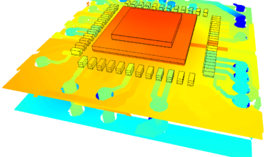
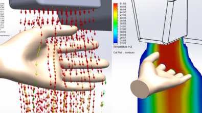
The vast majority of electronics cooling simulations performed today use a technology called CFD, computational fluid dynamics. A 3D CAD type definition of the components, PCBs, heatsinks, chassis, fans etc. are input. The equations that predict temperatures and air flow distribution are solved by clever number crunching executables. Finally the predicted temperatures and air flow can be examined in both graphical (CFD: color for directors) or tabular formats.

Why is there any question about how to model components, surely you would just define them as they exist in reality? It all comes down to data availability. Components (packaged silicon normally) are quite complex, incorporating many different parts, with different materials, from bond wires to lead frame, from a spreader to the die itself. Having to manually create all that for EACH component would be madness.
So, why not get such a description from the component manufacturer? Well, they tend to be quite secretive about the internals of their packages. There’s a lot of IP bound up in there, last thing they want to do is to provide a full 3D physical description of it to all and sundry.
Where does this leave the poor thermal engineer? With little data and pressing needs, a number of different component modelling methodologies have emerged over the last 20 or so years.
For this first part of this blog series we’ll cover the most common, a lumped block representation. A 3d homogeneous block with a single material.

In terms of data, the one thing that is available is the package footprint size, this is required for routing and manufacturing design (as is often the case with the more unique disciplines, thermal eats the crumbs that fall from the giants table). If you’ve got a footprint shape then the only other thing you’ll need to make a 3D model is the height. The component height can itself be quite rare, maybe less nowadays as component libraries become more refined and the need for mechanical interference checks becomes much more common place.
In reality a component will have a range of temperatures throughout it. The die being the hottest, the peripheral corners being the coldest. Components will be specified to work up to a maximum junction (die) or case (usually middle+top) temperature. How on earth can we get a range of temperatures out of a component model that is just one lump? Well, you can’t. Why not at least dissipate the heat in that block where the die actually is? Well, don’t bother, even if you did know how big the die was there is still no advantage in accuracy as you’re not modelling all the other heat flow paths in any detail. You can’t be half accurate when trying to be accurate. You’re just going to have to lump it, literally, and spread all the heat throughout your block representation.
 Last thing required is a material definition. A 3D thermal simulation requires that all solids have a thermal conductivity defined (to enable a steady state thermal prediction) and density and specific heat (to obtain the thermal capacitance) in addition if a transient thermal simulation is required. Well fear not young thermal engineer. We, your preferred vendor, have created a library of ‘typical lumped packages’ materials with values that will result in typical case temperature predictions when modelling your components as lumped blocks. If you buy the best you get the best, even when it helps you create a more accurate block.
Next time you see some nice piccies of an electronics cooling model, check out how the components are modelled. More than likely they’ll be blocks. Not the best approach by far, in fact it is the least accurate but easiest to define. How inaccurate? Hard to say as it varies a lot. On average I’d say between 10-30% error on case temperature rise with no indication of junction temperature at all. Not bad considering what you’re not representing.
9th October 2009, Ross-on-Wye