The Virtual and the Reality: A Brief History of 3D CAD Quality
 It was a sharply cold Illinois winter’s morning in 1989. I still remember it quite vividly. We turned into the parking lot at the Technical Center facility; an Englishman in the Midwest carpooling with his American colleague, both eager with anticipation at what we would see on the screen of the 32 MB Apollo DN4000 workstation—our most powerful machine. The previous Friday, prior to heading off for a weekend which included a football game at Chicago’s Soldier Field (I enjoyed all the American sports I could during my secondment), we had set the completed 3D solid model assembly of a back-hoe loader to generate a hidden line picture. That Monday morning, we hurried into the CAD room and there it was: A hidden line display generated by Romulus-D, the first Parasolid-based 3D solid modeling CAD system, set with a perspective view point from the operator’s cab. The log file diagnostics indicated that the operation had been completed successfully in around 27 hours! The picture looked great; the operator could see both ends of the back-hoe’s front bucket from his view point. Smiles all around.
.jpg")
It now seems absurd that anyone would happily wait for a hidden line picture to be created over a weekend. However, the traditional way to get this information—creating a physical production mock-up or scale model—would have taken several weeks and been hard to modify, not to mention very expensive. The value of a 3D solid model assembly here was clear. CAD had moved on from the 2D and 3D wireframe of the 1980’s, which being just an electronic drafting machine, added little value or integrity to the lines or pictures they created. Sure, it was easier to make changes or draw and measure lines precisely, but when CAD was introduced to my first job’s design office in 1985, its value to most engineers seemed limited. However, with 3D solid modeling (using boundary representation or B-rep in Parasolid’s case), the CAD model now had intelligence. Understanding topology connectivity and bounded volumes made it possible to generate hidden line pictures, calculate masses, and identify assembly interferences.
.jpg")
With the early days of solid modeling, there was a certain fragility with the balance between the geometrical and topological data structures. It was possible to check the validity of the solid body in terms of its mathematical “water-tightness,” but how necessary was this when the desired output was a drawing, rendered model, or file for machining? Strange B-rep based error messages—“geometry is inconsistent with topology,” “inconsistent loops,” and “face-face inconsistencies”— output from running solid checks and relayed to CAD designers and engineers using Unigraphics became folklore, continuing the mystification of solid modeling success as a dark art. “Fixing” the solid to remove these errors seemed to require alchemy. But should they throw away the solid and start again? Quicker alternative sanity checks were used during the modeling process. If the hidden line picture looked correct and gave the desired output, then you were good to go, even if you had “inconsistent loops.” Tiny edges and faces also proved problematic in solid models, and efforts were made to ensure these were not created, though often their creation was not really under the control of the user.
Tolerant Modeling and the Paradox of Quality Checking
In the mid-nineties, a project I was involved with to help Unigraphics design solid modeling-based parametric dies for a large automotive customer was a catalyst for the development and introduction of Parasolid Tolerant Modeling. This allowed bodies and faces to be “glued” together inside a tolerance zone rather than use existing intersection algorithms to Boolean (join) these regions, the complex underlying geometry and near-tangential conditions of which caused problems with performance and reliability of traditional Boolean methods. (An aside: It was interesting to see that, while Parasolid was trying to create a solid model to within fractions of a micron, the tool makers on the shop floors were hand “joining” die addendum surfaces using an angle grinder!) Tolerant Modeling introduced another consideration for the CAD user: What tolerance should he or she use and why?
As the UG solid modeling guru at the time, I was often asked by customers about Parasolid quality and checking. There was no definitive answer, just a paradox: A solid model that passes its B-rep checks, while being deemed being trustworthy and good, did not 100% guarantee that all future operations would succeed. Vice versa, models that failed some B-rep checks might still work for further downstream operations, like rendering or drawings, without the need to throw them away and start again. And don’t forget that the validation routine also could have false negatives. With no definitive answer possible, users tended to err on the side of caution. Passing the solid checking routine was upheld as sacrosanct, along with any other perceived best practices picked up along the way. Generally, this led to continued success with solid modeling and all of the great benefits that came with it.
Standardization and Improved Data Quality
Moving forward more than twenty years to the present day, there are millions of Parasolid-based CAD solid models being created and reliably used across many different industries and areas of PLM. Standards have been set up to check CAD data quality, such as SASIG PDQ for Automotive. CAD data quality is pertinent, particularly during the import and translation of solid models from one vendor to another. While there is still no silver-bullet guarantee when it comes to the results of these checks, they help indicate when things will likely go smoother where there are no serious failures.
The good news here is that Parasolid is now a very mature and reliable B-rep modeling kernel. Consequently, NX is much more robust than UG was 20 years ago when creating solid models. This is due in part to implementation improvements in NX. Many of the checks still used today are legacy from bygone times and far less likely to fail. Thus, many legacy best practices have been made irrelevant by continuous improvements in Parasolid and NX.
Up to this point, the focus has been on data integrity of the b-rep model and how to achieve a good perception of its quality. This is important, of course, as the solid model forms the foundation of the CAD part, but what other CAD quality checks are worth considering? What benefits might these offer?
Once you have a good, robust solid model, there are other ways that NX can interrogate and validate this virtual CAD model for quality. Quality here refers to a model’s fitness of purpose, the reality of its use throughout the organization, and adherence to a company’s standards and best practices. Does the part or assembly meet its critical design requirements? Can the part be manufactured? Can the assembly be assembled? NX has dedicated CAD validation products to help customers answer all of these questions, as well as to check the part or assembly’s integrity and quality against all of these criteria.
Achieve Success with NX Check-Mate, DFMPro for NX and NX Requirements Validation

The ability to create or import and translate CAD models that are high quality, fit for purpose, and consistently follow company best practices and industry standards, is integral in helping our customers achieve success. NX Check-Mate is an automated tool that allows NX parts, assemblies, and drawings to be validated against a set of pre-configured checks. Over 320 checks are supplied out-of-the-box for modeling, drafting, assemblies, welding and many other areas. “Validate early and often” is the mantra for best practice, producing the best and most fit-for-purpose CAD models at the early design stage of the product lifecycle. Check-Mate also allows for geometry and solid model quality checks to the SASIG-PDQ standard.

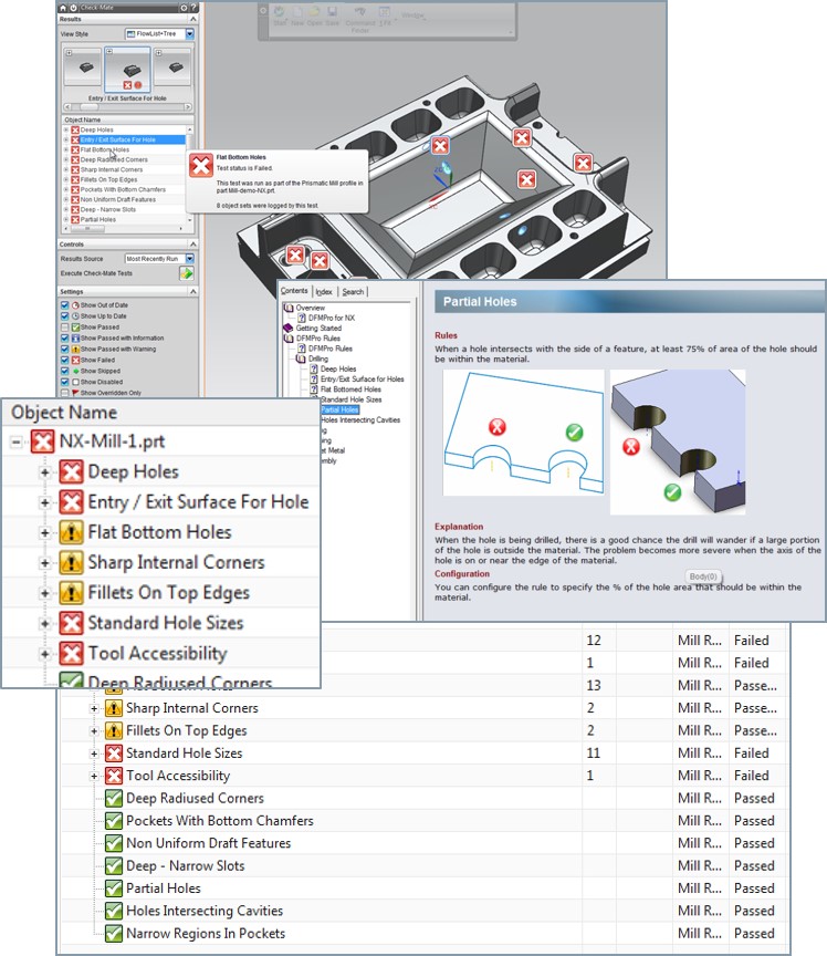
Users can check parts for manufacturability and assembly quality using the DFMPro for NX add-in. This product uses Check-Mate as its framework and provides over 100 additional out-of-the-box checks for machining, sheet metal, injection molding, assembly, casting manufacturing processes, and more. NX part quality is improved with this tool in respect of reducing rework cost due to manufacturability or assembly errors. Importantly, finding these problems early in the design phase before these operations take place can save companies huge amounts of money.

NX Requirements Validation is the tool available to all NX users that allows a part or assembly’s physical properties—weight, dimensions, or assembly clearances—to be checked against the critical and desired requirements for the part or assembly. These requirements can be imported from requirements data sheets stored in excel or HTML and stored within the NX part or referenced as a Teamcenter managed set of requirements. With this tool, whenever any requirement fails to meet its criteria, it can be identified automatically.
Check-Mate, DFMPro for NX, and NX Requirements Validation all use the HD3D framework with its highly visual navigation tools and tags to identify problem areas and find problems. This adds usability and consistency during this CAD validation and quality checking process.
Things have come a long way since the early days of 3D solid modeling in the ‘80s. While the solid model integrity and accuracy is still an important starting point, CAD designers and engineers now also have at their hands a variety of out-of-the-box checks and add-on tools to help them validate downstream CAD data quality in their models. This makes for more robust products that meet both company and industry standards, their functional requirements and their manufacturability. It’s how Siemens PLM Software and NX help you transform the virtual to reality.