NX | Tips and Tricks | PMI

In the world of digital product design, precision and clarity are essential. Whether you’re designing a simple bracket or a complex assembly, ensuring that your design intent is communicated clearly to manufacturing is critical. This is where Product Manufacturing Information (PMI) becomes a key part of the process. PMI includes all the critical annotations and metadata that define how a part should be manufactured. This includes dimensions, tolerances, materials, surface finishes, and more. When used effectively, PMI eliminates ambiguity, reduces the risk of production errors, and ensures consistency across production runs.
However, as models become more intricate and the demand for faster turnaround increases, managing PMI manually can become a bottleneck. Fortunately, Designcenter NX offers a suite of tools that can help streamline this process. In this Tips and Tricks, we will explore how to enhance your PMI workflow using model-based definition (MBD) rules, feature control frames, and annotation orientation settings. These tools improve efficiency, help enforce design standards and enhance communication between design and manufacturing teams.
Automating PMI with MBD rules from the reuse library
One of the most powerful yet underutilized features in NX is the reuse library, particularly the MBD logical rules it contains. Traditionally, users add PMI by manually selecting dimensions and annotations from the toolbar. While this method works, it can be time-consuming and inconsistent, especially when working across large teams or multiple projects. MBD rules offer a smarter and more reliable alternative.
Top tip: Apply PMI faster with MBD logical rules
Whether you are working on a single part or a large assembly, MBD rules help ensure that your documentation is consistent and compliant with design standards.
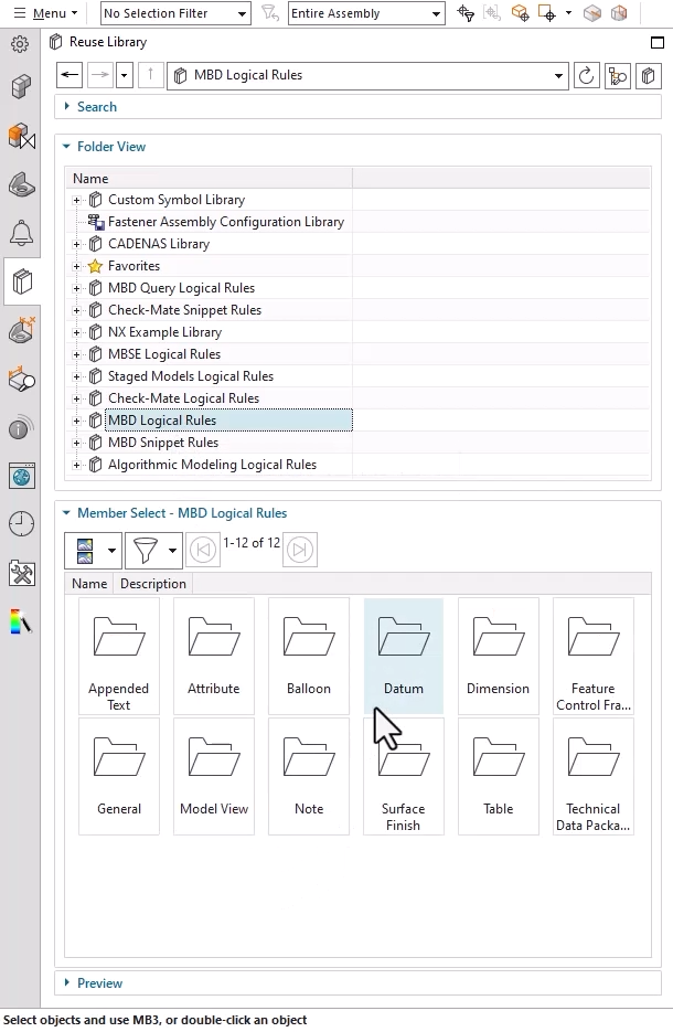
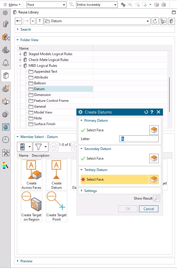
MBD logical rules are predefined templates that automate the application of PMI elements. These rules are organized into folders such as Dimensions, Datums, and Feature Control Frames, making it easy to find the right rule for your specific design needs. Applying a rule is simple. Browse to the appropriate folder, double-click the desired rule, and follow the guided prompts that appear in the command window. The system then applies the rule to your model, ensuring that the correct annotations are placed in the right locations with minimal manual input.
This approach not only saves time but also enforces consistency across your designs. By using standardized rules, you reduce the likelihood of missing critical information or introducing errors due to manual oversight. It also makes it easier to onboard new team members, as they can rely on the rules to guide them through the annotation process without needing to memorize every detail.
Defining geometric tolerances with feature control frames
Once your basic PMI is in place, the next step is to define geometric tolerances using feature control frames (FCFs). These annotations are essential for specifying how much variation is allowed in the geometry of a part. In NX, adding an FCF is a straightforward process, but doing it efficiently requires a bit of know-how.
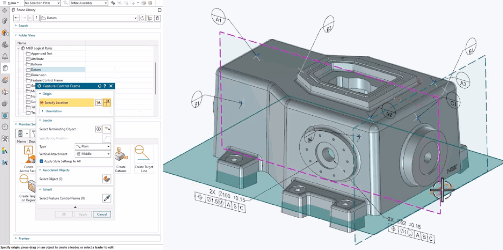
To begin, select the Feature Control Frame command from the Annotation group. You will first be prompted to choose a placement plane. This is where the FCF will appear in your model. Next, select a terminating object for the leader line, which visually connects the FCF to the relevant feature. Once the location is set, you can define the contents of the frame using the toolbar at the top of the screen. Here, you will specify the geometric characteristics, such as flatness, perpendicularity, or position, along with the tolerance value and any datum references required.
This process ensures that your tolerances are clearly defined and visually linked to the appropriate features in your model. It also helps downstream users, such as quality control inspectors or CNC programmers, understand exactly how the part should be inspected or machined. By taking the time to set up your FCFs correctly, you can avoid costly misunderstandings and ensure that your parts meet design specifications every time.
Improving readability with PMI note orientation settings
As your model becomes more complex, it is important to ensure that your annotations remain readable and accessible. One common challenge is that PMI notes can become difficult to read as you rotate or zoom in on the model. To assist with this issue, NX provides orientation settings that allow you to lock the position and size of notes relative to the screen.


To access these settings, right-click on a PMI note and select “Settings” from the context menu. In the dialog that appears, you will find two key options. The first is “Keep note parallel to screen,” and the second is “Lock size and position.” Enabling these options ensures that the note remains legible regardless of how you manipulate the model. This is especially useful during design reviews or when presenting your model to stakeholders, as it keeps important information front and center.
Top tip: Customize note behavior for better visibility
Use the orientation settings to keep PMI notes parallel to the screen and locked in size. This makes it easier to navigate your model and ensures that important notes remain readable during presentations or design reviews.
Final thoughts
Incorporating PMI into your design process is essential for ensuring that your parts are manufactured accurately and efficiently. But managing PMI does not have to be a chore. By leveraging tools like MBD logical rules, feature control frames, and annotation orientation settings, you can streamline your workflow, reduce errors, and improve communication across your team.
To summarize, here are the key takeaways:
- Use the reuse library’s MBD rules to apply standardized PMI quickly and consistently
- Add feature control frames to define geometric tolerances with precision and clarity
- Adjust note orientation settings to keep annotations readable and accessible throughout the design process
These tips can help you work more efficiently and ensure that your designs are not only innovative but also ready for production. Thank you for reading and stay tuned for more NX tips and tricks.
Continue your journey with NX
Watch the Chamfer Cage on Subdivision Bodies Tips and Tricks video here ▶️
Watch the Lattice Structures Tips and Tricks video here ▶️
Take me to the NX design blog 📚