PCB traces and impedance planning

Minimizing insertion loss: Why understanding trace width is critical at high frequencies

Material matters An engineer asked me recently about the relationship between trace width and insertion loss while adjusting dielectric height…

fabricator etching a PCB

Etch effects exposed: discover where your copper really goes

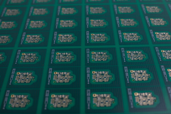
Etching inner layers involves cleaning the copper on both sides of the piece of laminate, applying a photoresist, exposing the photoresist to create the inner layer pattern, developing the resist, etching away the unwanted copper, and removing the etch resist. This process is automated in most shops and the chemistry is automatically monitored. As a result, the accuracy and repeatability is quite good. It is possible to etch inner layer traces using this process to an accuracy of ±0.5 mils. This accuracy control helps keep impedance within the tolerances required for transmission lines.

dielectric material loss

Cutting your losses – loss planning and you

Loss planning – What is the best laminate for a loss budget of x dB for y inches?  I was thinking in terms of Panasonic Megaton (sic) 6 or something like it.

copper thickness in PCBs

Copper thickness: Closing the knowledge gap to design success

Copper thickness determination of rolled and electro-deposited (ED) copper foil by weight provides far more accuracy than contact-thickness gauges. Since the topography of treated foil varies greatly, and since the density of copper is known, weighing a 1-by-1 foot sheet is the best way to determine the average thickness of a sheet of copper.  So formally, the unit that we refer to as “ounces” is actually ounces per square foot.

Crosstalk along traces

Your #1 defense against a crosstalk crisis

It’s been some time since I’ve seen an article on crosstalk, so I decided to take the opportunity to walk…