Heat exchanger – Understanding my latest invention
The making of a maker
Have you ever wondered what makes a maker and what the future of engineering might look like? Let me take you on a little field trip and explore the matter in a hands-on fashion.
One day, I decided to attempt to see if I could save energy without breaking the bank. Everyone is currently feeling the bite of rocketing energy prices and the pinch of global warming. So I set myself a challenge. To boil down the question of how to improve the energy efficiency of an otherwise solid house, dating back to the early 70s, at less cost than building a new one. Introducing up-to-date concepts, such as a central regenerative ventilation system, if feasible at all, typically means substantial building works with a slightly uncertain outcome.
An obvious solution could be to have small recuperative ventilation units for each room without introducing extensive voluminous pipework across the building. A quick survey for products didn´t however lead to completely convincing results.
In a traditional scenario this would be about the point where the story ends, as designing, optimizing and manufacturing products such as these typically involves big money and a crew of highly specialized senior experts mastering their respective engineering tools. These would cover design (CAD), simulation (CFD) and manufacturing data preparation (CAM). While I´m still working on the issue of getting my hands on big money, the following story describes, how a broader style of engineering could look like, based on a set of tools handled by one more generally trained engineer – the future industrial maker.
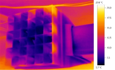
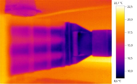
Incidentally, engineering is not only my profession but a major part of my lifestyle. Hence, I happen to run 3D-printers, a thermal imager and a few other gadgets in the lair hidden underneath the house. However, earlier attempts on counter-flow heat exchangers turned out to be bulky and not overly effective.
Freeing my designs from the limitation of traditional manufacturing techniques
Whilst re-thinking the matter, I found that I had fallen into the same trap as I had on previous occasions. I was focused on designing for 3D-printing and not freeing my mind of the limitations of traditional manufacturing techniques. In this case those of extruded plastic profiles, which are problematic with undercuts and changing cross sections. 3D-printing however largely doesn´t have to deal with these issues. Hence the design approach could follow much more physical requirements, than be limited to designs known from catalogues of tubing suppliers utilizing traditional manufacturing processes. Digging in my memory for remnants of aerodynamics lectures, model building attempts and projects with our gas turbine business I concluded that the exchange efficiency of a heat exchanger would benefit from thin walls and a certain amount of turbulence, which could be achieved by a rotation of the airflow and variation of the cross section. In an ideal laminary flow, only the one outer “lamina” (layer) exchanges heat with the exchange surface, leaving the core of the flow largely unchanged (which is not the point of a heat exchanger).
Spiral vase
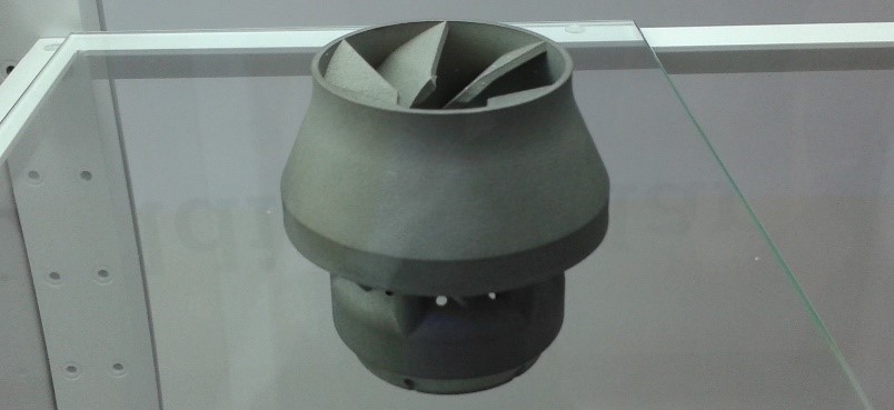
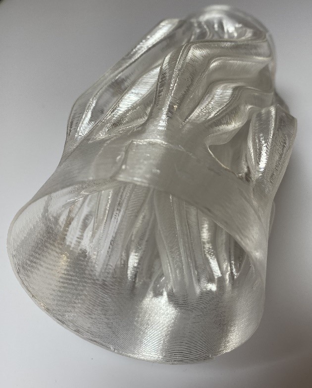
The good news is that most 3D-printing software offers a rarely used slicing mode, “Spiral Vase”, that allows you to print a single-layer surface (typically around 0.4mm thin), is rather fast (it prints continuously, in one go, without interruptions) and works well with shapes, that change gradually (like aerodynamic shapes).
The remaining challenge was now to define an ugly vase single body, which, despite having only a single cross section, provides a high surface and some channel-like structures to guide the flow. In a first shot, this could be achieved by a simple sketch and a few steps in CAD; which was no rocket science thanks to the employee- (aka academic-) edition of Siemens´ Solid Edge CAD package.

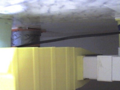
Of course, this needs to be put within a tube to contain the outer flow and requires the usual bits and bobs to connect to the rest of the world. In this case this materialized in the shape of PVC-wastewater pipes (newly bought, there are limits to recycling), which come as part of a vast modular system with many options – there´s no point in printing commodities.
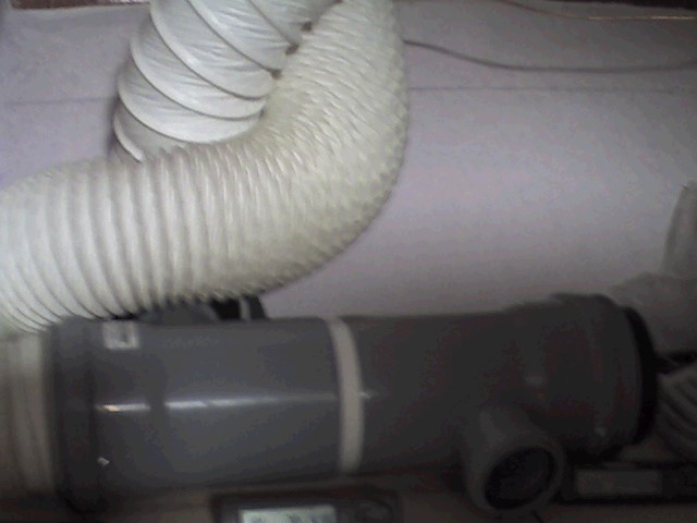
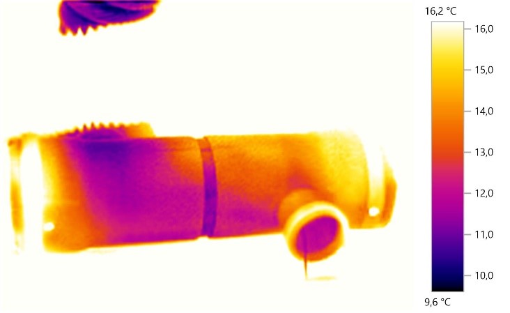
This contraption was powered up by two bilge blowers and equipped with several thermometers. Air speed was measured by means of an anemometer. Although there was a notable effect, it was not an impressive result. The incoming air gained around 5°C while passing the heat exchanger at around 5m/s. Somewhat more effective than opening the window, albeit that would be quicker and not as noisy.
Considering this a satisfying result for a first attempt, the question now, is what the next step could be? Obviously modifying the pattern of the exchanger (more and smaller quasi-channels, better distribution over the cross-section area, ..) might improve the efficiency; overall, more length, a higher rate of twisting, better conducting material and outer insulation might help. However, where to start and which improvement would be the most rewarding? Admittedly, I was having a lot of fun, but this was all very time consuming. Consequently (and with spring coming up), the whole project went into hibernation.

Refreshed from hibernation
.. until, in my professional life as an expert for manufacturing technologies and automation, I decided to build up some knowledge in the field of 3D-flow simulation (Computational Fluid Dynamics – CFD), namely “Simcenter STAR CCM+”. Siemens has quite a portfolio of simulation software, covering fields as diverse as CFD, computational chemistry, electromagnetics, automation, process workflows and many more. One of the privileges of being part of Siemens is the opportunity to work with products that are leaders in their field and hence often used, when cutting edge (aka “cool”) topics need to be addressed.
While the printed heat exchanger introduced above is rather a lukewarm (literally) than a cool example this personal interest helped me to stick to my plan to delve into the demanding topic of CFD (or rather scratch the surface a little deeper, based on a single example). How to begin? Coming from the proud field of CAD, where the focus is, rather intuitively, on the design of tangible objects, I first began to try a few tutorials and was struck by encountering a different paradigm: this is, in a first step, rather about the design of fluid bodies and the description of their boundaries, properties and relations. Hence, CAD data comes in handy to describe the outer shape of the fluid bodies, but rather than native CAD data, surface meshes are what counts to circumscribe the fluid bodies. Of course, there is built-in functionality to convert CAD data to surface meshes (and more), but CAD data is merely feedstock for the process; consequently, there is a comprehensive environment for working with surface meshes.
Getting into a right mesh!
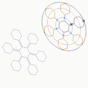
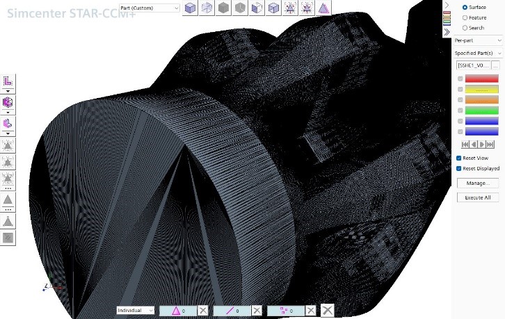
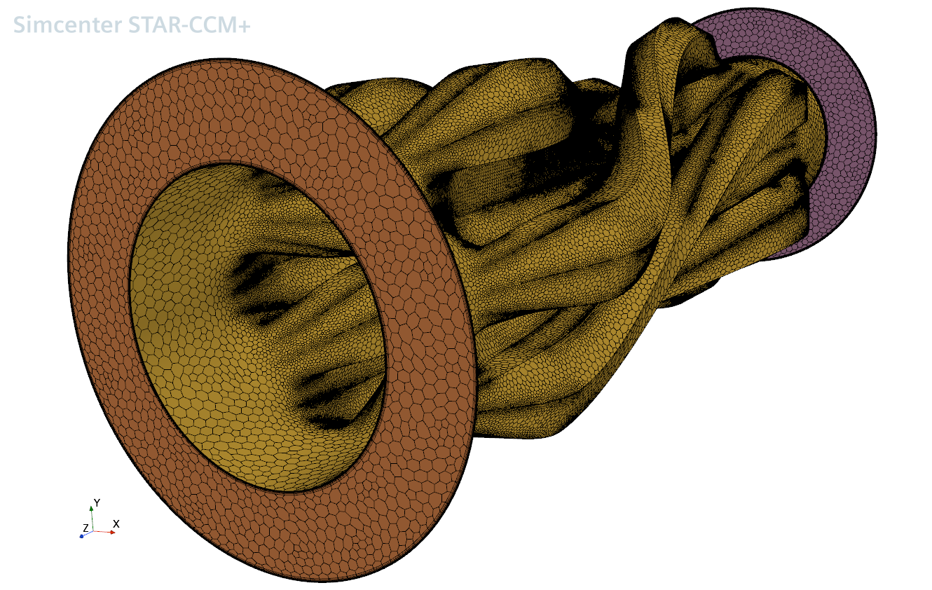
The body imported from CAD is split into several surfaces, which are then used to assemble the fluid bodies, parting walls, fins, etc. in question. However, while in our example the hollow shell of the heat exchanger would be a perfectly complete part in the CAD model, for the CFD model “end caps” (inlets and outlets) also need to be modelled to fully close the space of the fluid.
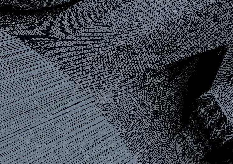
The body defined by the surface meshes resembles what is known to the 3D-printing community from STL- and 3MF-data, criteria such as watertightness, orientation of the surface normal or distorted triangles may ring a bell or two amongst them. However, there are differences: while in 3D-printing the surface mesh is, to my knowledge, no longer needed after slicing, in CFD the structure of the surface mesh influences the generation of the volume mesh of the fluid body and thus the exchanges of energy and matter between adjoining bodies. Hence there are requirements for the congruency of adjoining surface meshes, addressed by a function called “imprint”, which aligns the structure of the surface meshes.
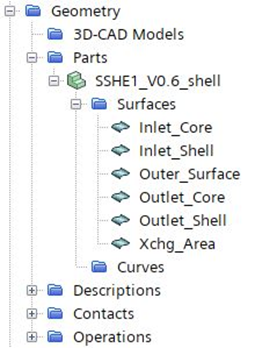
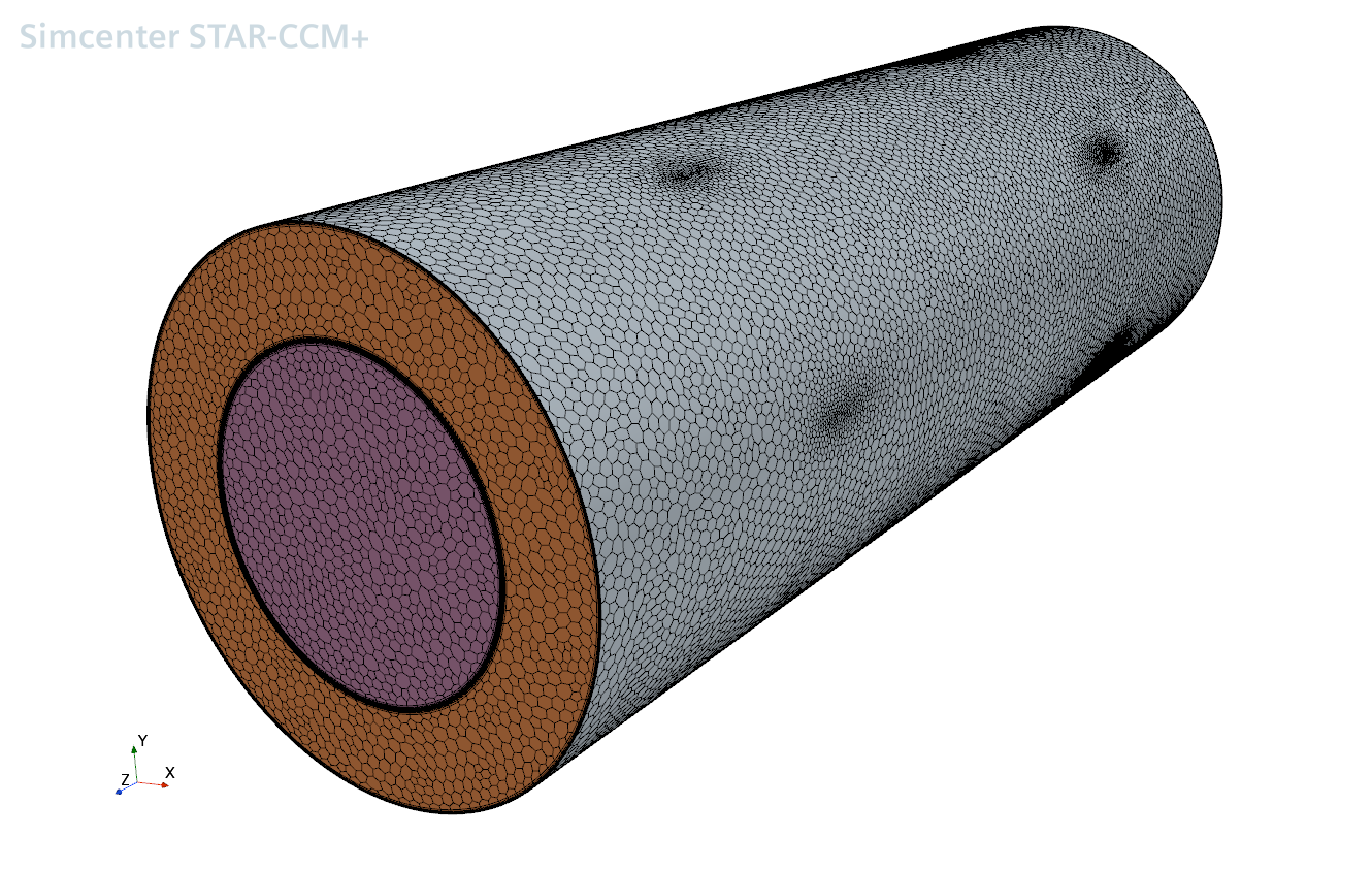
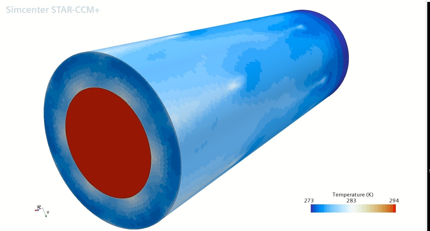
After disassembling the CAD data into surface meshes, re-assembling them and adding “end caps” for the openings the result is two adjoining “regions” which circumscribe the respective fluid volumes; one for the outward flow (initially warm exhaust air; the stream within the exchanger surface) and one for the inward flow (initially cold fresh air; the stream between the exchanger surface and an outer cylindrical wall (mostly not shown)). Overall, in this example there are six surfaces from which to assemble the regions: heat exchanger (the complicated looking bit), outer shell (cylinder, not shown) and two endcaps (inlet, outlet) for the inner and outer region respectively. So much for the geometry.
But how does the simulation happen? The fundamental idea is to fill the “regions” with a static volume mesh consisting of cells, the calculations (energy and matter exchanges between neighbouring cells, state equations dealing with temperature, velocity, pressure, etc.) are then performed for each cell in each simulation cycle. While the cells are describing little volumes firmly located in space, rather the description of the fluid is moving through them.
In order to come from the description of the geometry to this, more input is needed: the surfaces of the regions are defined as “boundaries”, basically it is possible to choose from different types of orifices (used here: pressure outlet, stagnation inlet) and walls, attributed with physical behaviours and properties. I later learned from a much more knowledgeable colleague that my somewhat incidental choice of in- and outlets without a velocity component only made another somewhat unusual design decision work: the use of a single “continuum” for both inward and outward flow; a more experienced engineer would have chosen two continua respectively, allowing for opposing initial flow velocities.
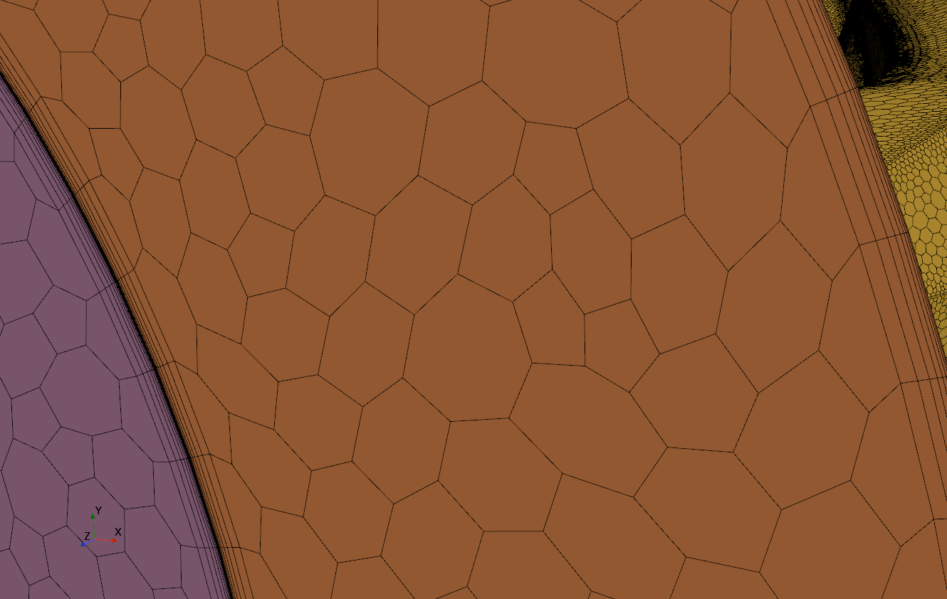
The definition of continua describes what´s actually the stuff in the fluid volumes, within this case simply (default-)air. However, one key ingredient is still missing: the volume mesh. As indicated above, this rather describes the level of detail of the simulation, depending on the location in the respective region. This addresses the fact that different physical effects prevail in different parts of a flow: at the boundary between a fluid and a solid life is much more turbulent for the fluid than, e.g., in the middle of a laminary flow. While the shape and size of the cells is not directly a physical property, it is a means to adapt the accuracy of the simulation to the prevailing physical effects. To put it bluntly: more (hence smaller) and better adapted cells are needed, where the action is, e.g., in turbulent areas and the boundary layer. Hence there are several types of mesh generators to choose from, manually, if the automatic selection needs to be overridden by an expert.
The geometry and the mesh prepares the stage for the play to happen, but what´s the script?
The next required ingredient is the description of the applicable physics models. Obviously there´s a difference between a supersonic flow and a gentle breeze, the latter being closer to what (presumably) happens here. While the underlying physics, aka laws-of-nature, are the same, the art of creating a useful simulation is to abstract and simplify the problem to such an extent, that a meaningful result can be achieved on real world hardware in a timespan that allows leaving for a cup of coffee, rather than a gourmet weekend. So, the choice of things to neglect and numerical approximations to select is really a crucial point.
How did I cope, not being an aerodynamics engineer? Quite frankly, I began with a very basic tutorial and copied the settings, this clearly not being the optimum solution. However, it permitted to come to a very first working model. Based on this I later began to modify the physics models and the mesh, by playing with different turbulence models, boundary layer thickness, surface roughness, etc.; whilst bearing in mind the indicative measurements from the test setup. So, in a quite playful manner, it was possible to see where differences occurred, what brought my workstation to a limit (interestingly, seemingly more frequently memory bandwidth than CPU/GPU performance), and so on.
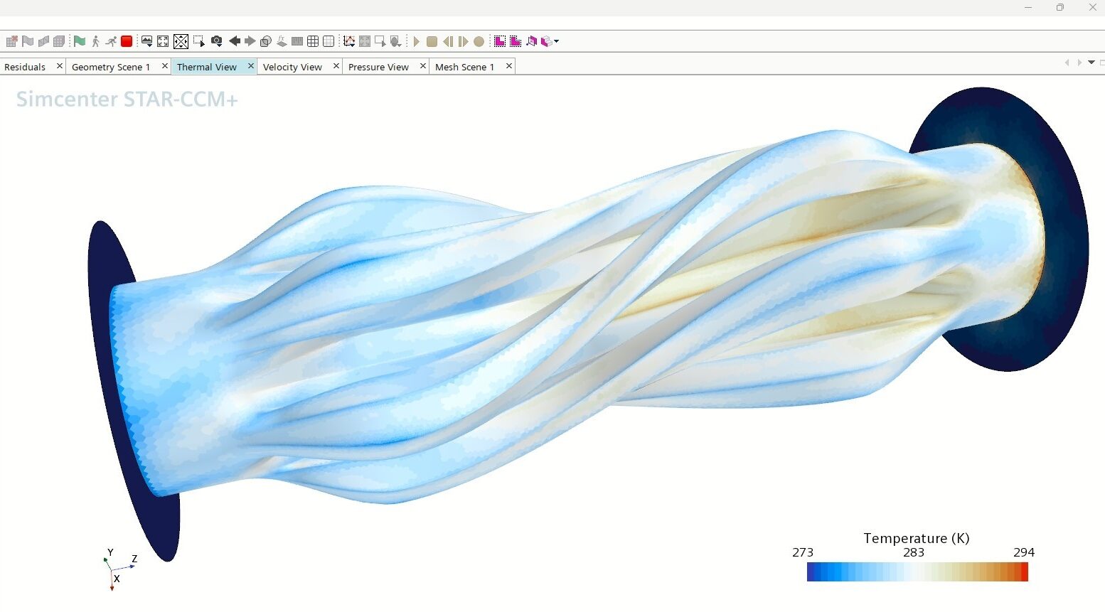
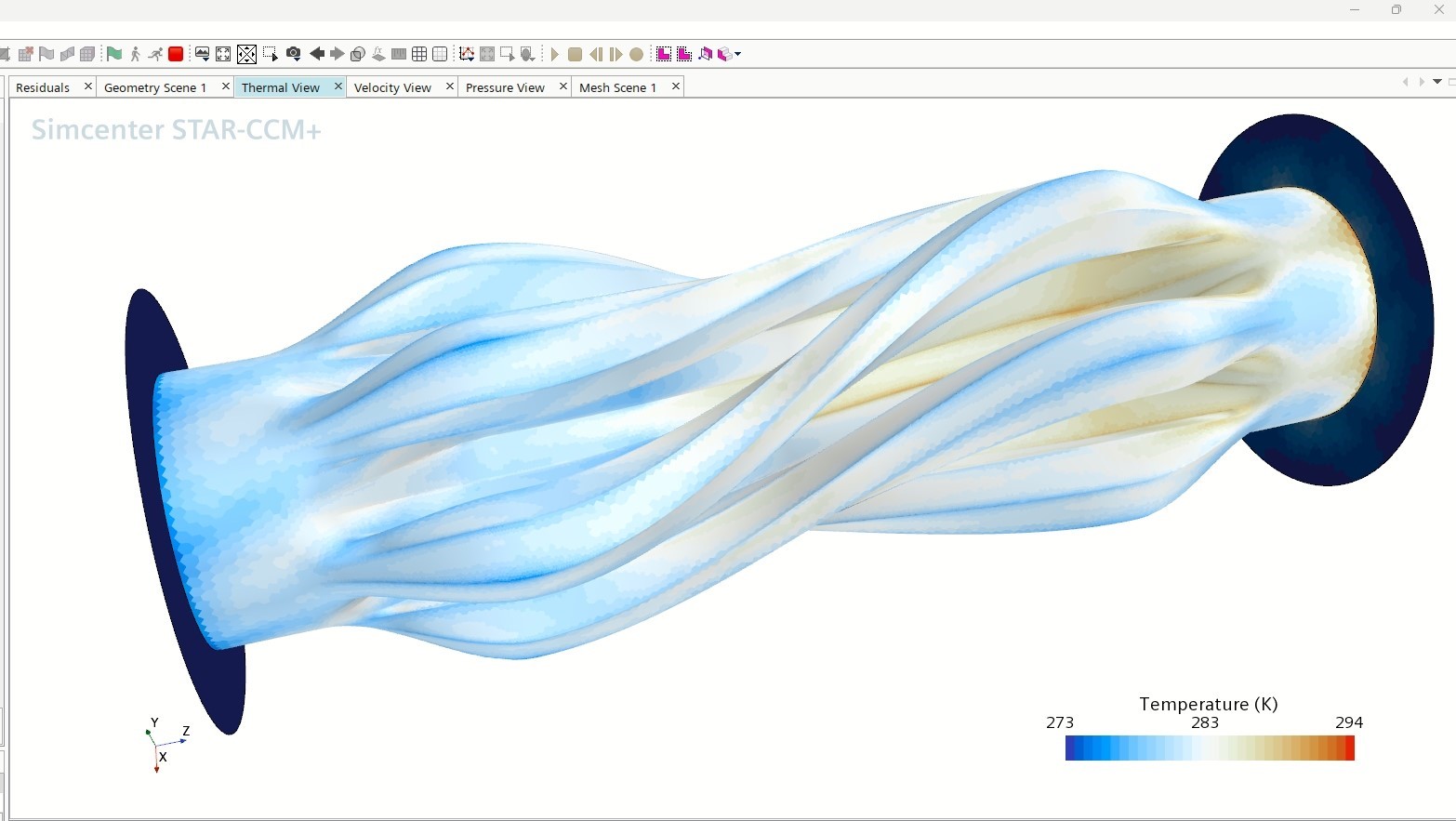
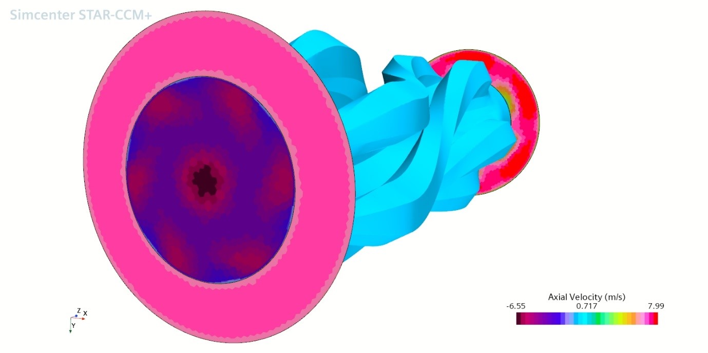
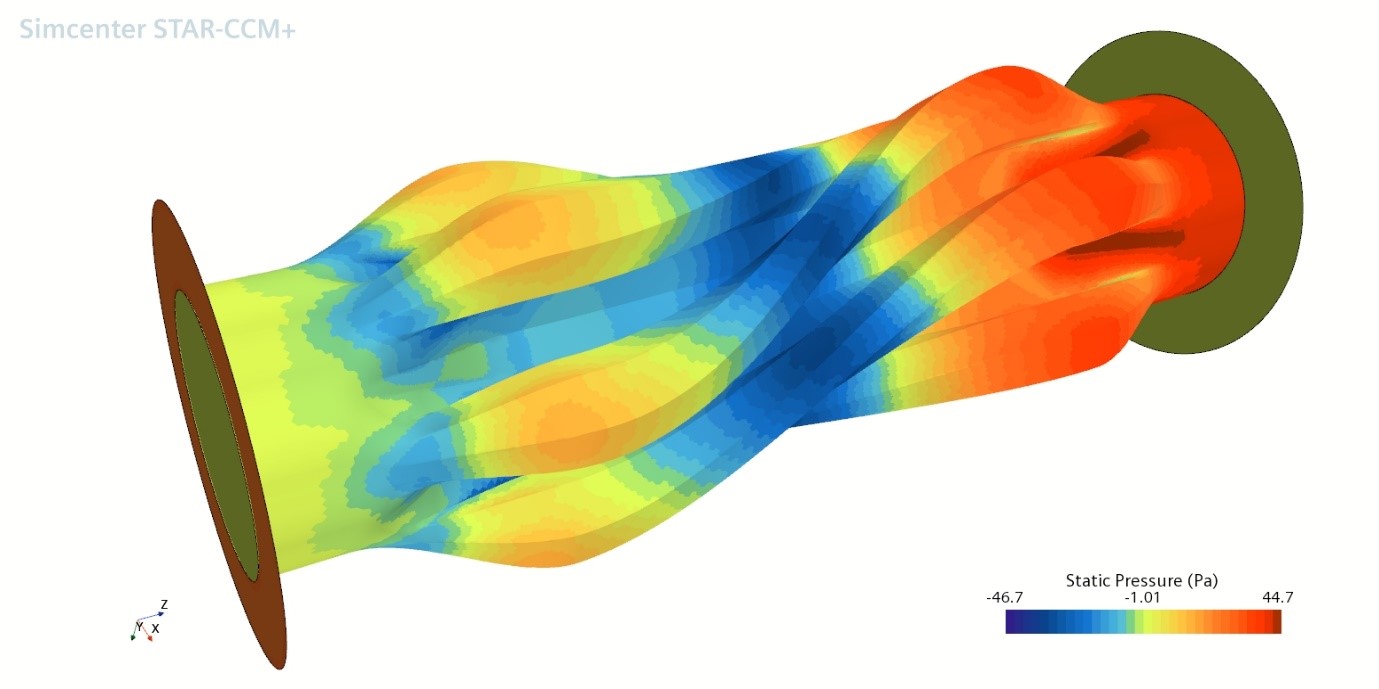
After some more minor preparations and defining a few views (velocity, speed, temperature – much more is possible) I started the whole thing and watched.
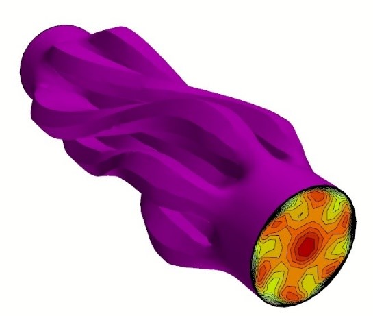
Admittedly, a somewhat moving moment to see a sort-of-plausible velocity distribution at the outlet, reflecting the complex overall geometry – rather the point of this design.
Learning from my mistakes
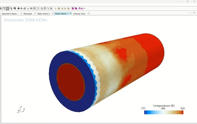
However, it soon became clear that something was going wrong. On the left one can see the cold from the outer inlet bringing down the skin temperature of the cylinder, while the pressure begins to bring the fluid in motion. So far so good and very promising, but why, after some time, the whole thing looks like the two volumina don´t take notice of each other at all?
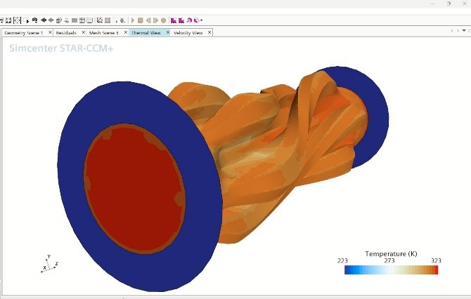
The avid reader may have noticed that I didn´t describe how to achieve the heat transfer, and that´s indeed where this particular devil was in the detail (coming after myself and the not-so-avid readers). What I depicted above makes only use of the heat exchanger surface in order to shape the two volumina, thus providing only an aerodynamic property, and otherwise behaves like an adiabatic wall (here, no useful thermodynamic property). There are several ways to model heat transfer; in this case, the surface was then attributed to be a “baffle”, fulfilling the role as an “interface” to be supplied with a few more parameters. It pays to maintain an overview of the parameters and consider plausibility from time to time; at one point a simulation run reached a temperature around the melting point of tungsten, after the first rush of enthusiasm (“.. ultimately the path to cold nuclear fusion?”) it turned out to be a bad setting.
It must be stated that this mode of self-teaching agrees well while done in-parallel with other work, as the simulation runs took some time (and indeed helped to heat my home office cubicle with the workstation gently number-crunching along). From time to time there were new results, which usually required trying other parameters or investigating some technical challenge and then launching again.
Ultimately the results began to turn plausible and permitted to begin with variations, e.g. decrease volume flow, temperature difference or to change the material from plastics to aluminium. In a more professional scenario this would be the point where the benefit of the simulation would begin to materialize by saving lots of physical prototypes and allowing investigation of the possible benefits of (yet) “unreachable” implementations (such as the use of 0.4mm thick aluminium).
In this scenario, it helped me to better understand my hands-on invention and opened new ways to improve it.
Conclusion
Coming back to the initial question the silhouette of the “future industrial maker” may have become a bit more concrete. With an increasing amount of knowledge and supportive behaviors embedded in software tools, them being ideally integrated to such an extent that the engineer can focus on the actual creation of value rather than, e.g., tedious troubleshooting of interfaces, broadly educated individual engineers will be able to handle engineering workflows from the initial idea to the actual production of the respective product.
Will this particular heat exchanger design save the world? Presumably not, but it might turn into a nice DIY self-help solution.
(However, topology optimized heat exchanger designs might be an even more interesting approach, but that´s another story ..)
Disclaimer
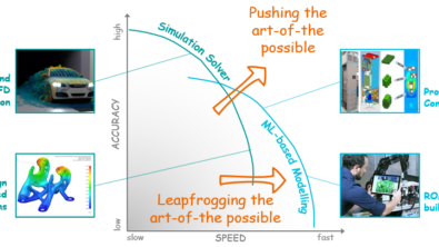
This is a research exploration by the Simcenter Technology Innovation team. Our mission: to explore new technologies, to seek out new applications for simulation, and boldly demonstrate the art of the possible where no one has gone before. Therefore, this blog represents only potential product innovations and does not constitute a commitment for delivery. Questions? Contact us at Simcenter_ti.sisw@siemens.com.