3D Collision and Clearance Checking
 In my last blog post, ECAD-MCAD co-design for First Pass Success, we reviewed how an efficient ECAD-MCAD co-design process can be an enabler for design teams to eliminate costly electro-mechanical issues during new product development. That blog focused on the benefits of the IDX data format for expediting cross-domain collaboration. This time we’ll extend the conversation, and discuss the benefits of leveraging the MCAD data within the ECAD domain to perfrom 3D collision and clearance, checking in the context of the product housing/enclosure.
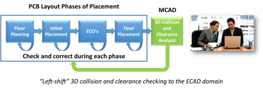
Checking for potential electro-mechanical collision or clearance issues associated with a product is usually only performed in the mechanical domain. An efficient ECAD-MCAD co-design process facilitates left-shifting the checking to also be performed in the electrical domain during the various phases of component placement; thereby ensuring a more robust product. As a reminder, “left-shift” within the engineering space is often used to describe the act of moving (or shifting) a task that would normally occur towards a latter phase of the design process to also occur during an earlier phase in the design process. Generally speaking, shifting the task does not necessarily eliminate the need for the task later in the process; rather, it is intended to both reduce the dependency and improve the result.
It is important to note that when leveraging the MCAD data within the ECAD domain, all mechanical data can be utilized including the enclosure, standoffs, mounting hardware, etc. In order to check the PCB in the context of the MCAD data the ECAD designer must:
- Import the MCAD data
- Align (or mate) the MCAD data with the PCB
- Define the 3D clearance rule or rules
- Perform the 3D design rule checks
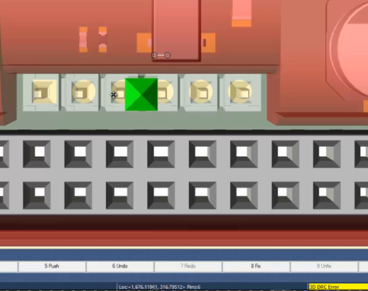
By default, Xpedition 3D clearances have a general definition with Optimal XY and Optimal Z values that are used for all mechanical objects. Minimum XY and Minimum Z values can also be defined. Furthermore, users can define unique definitions for Optimal XY, Optimal Z, Minimum XY, and Minimum Z to specify smaller or larger clearances between certain pairings of electrical and mechanical objects. Any 3D clearance values specified are applied during both interactive DRC and batch DRC. With Xpedition, 3D collision and clearance checking can be used to extend the benefits of an efficient ECAD-MCAD co-design process. A product demo entitled 3D Collision and Clearance Checking, along with a webinar entitled Xpedition 3D Layout Design, are both available for more in-depth information.


Comments
Leave a Reply
You must be logged in to post a comment.
Thank you, Mr. Craig Armenti. I am really glad that you are here to tell us about latest technologies used in PCB and IC package designs. I hope we will see your next post soon with latest guidelines or technologies.