What’s the deal with those wire’s and reg’s in Verilog
A unique concept most beginners have trouble grasping about the Verilog, and now the SystemVerilog, Hardware Description Language (HDL) is the difference between wire’s (networks) and reg‘s (variables). This concept is something that every experienced RTL designer should be familiar with, but there are now many verification engineers with no prior Verilog experience trying to pick up SystemVerilog for their testbench. Verification methodology courses tend to concentrate on the Object-Oriented programming aspects of testbench design, but do not cover this topic thinking that it is for designers only. Not true. If you have to communicate with a DUT then you need to understand the difference between wire’s and reg’s (nets and variables).
Anyone tasked with having to design or verify a piece of hardware should have some basic programming skills and understand the concept of a variable. If not, you had better stop right here and brush up on some programming basics. The key concept that you need to take away from programming is that you write a value into a variable and that value is saved until the next assignment to that variable. This concept is referred to as a procedural assignment which is part of executing an ordered set of statements. An HDL may add some notion of time in between assignments and other statements. The last assignment determines the current value of the variable.
| Combinatorial Logic | Sequential Logic |
|
|
Initially, Verilog used the keyword reg to declare variables representing sequential hardware registers. Eventually, synthesis tools began to use reg to represent both sequential and combinational hardware as shown above and the Verilog documentation was changed to say that reg is just what is used to declare a variable. SystemVerilog renamed reg to logic to avoid confusion with a register – it is just a data type (specifically reg is a 1-bit, 4-state data type). However people get confused because of all the old material that refers to reg. Just forget about it and use logic from now on.
Another distinctive characteristic of an HDL is that it models massive amounts of parallel processes. At the lowest level of digital design, every primitive gate (AND, OR, DFF) is an independent concurrent process. Modules are containers representing processes modeled at different levels of abstraction. Groups of primitives and modules pass values to each other via networks of signals. In Verilog, a wire declaration represents a network (net) of connections with each connection either driving a value or responding to the resolved value being driven on the net. The output of each of these concurrent processes drives a net in what is called a continuous assignment because the process continually updates the value it wants to drive on the net. There are various ways to declare a continuous assignment, all of which represent permanent behaviors:
wire A, B, C; assign A = B| C; // continuous assignment construct. or(A,B,C); // gate-level instance terminal connection mymodule m1(A,B,C); // module instance port connection 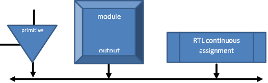
Although these are all different forms of continuous assignment constructs, none of them directly assign a value to the net like a procedural assignment would. All of the values being concurrently driven onto the net are passed into a built-in resolution function. The result of that resolution function is based on the strengths of each driver representing the hardware technology in use. For example, an interrupt request signal might use the wired-or (wor) kind of net to indicate that at least one device is driving a ‘1’, otherwise it will resolve to a ‘0’. Some signals will have weaker pull-up/down resistors that will be overridden by the values of a stronger driver. Most technologies do not allow driving different values on the same net and the net will resolve to an unknown ‘x’ when that happens. In this case only one driver is actively assigning a ‘0’ or ‘1’ and the other drivers are effectively turned off by driving a high-impedance or ‘z’ state. The consequence of this is that a bi-directional port must be modeled using a net in order to have multiple drivers on either side of the port.
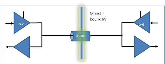
See my paper, The Missing Link: The Testbench to DUT Connection for an example of modeling bidirectional signals along with other tips for connecting the Testbench to your DUT.
It turns out that the vast majority of nets in a design will only have a single driver, so no strength information or resolution function is needed. SystemVerilog added a feature that allows a single continuous assignment to drive a variable. The expression driving the continuous assignment is assigned to the variable every time the expression changes its value. As soon as you have more than one driver or need strength information, you must go back to using a net. You cannot mix procedural and continuous assignments to the same variable. The reason for that restriction is that there is no way to resolve the “last write wins” semantics of a procedural assignment with a driver that wants to continually assign the variable (i.e. when is the last write finished and the continuous assignment supposed to take over?).
In summary, you should now be using logic for 4-state variables (or bit for 2-state variables) to represent all of your single drive signals. Any signal with more or the potential for more than one driver should be declared as a wire.


Comments
Leave a Reply
You must be logged in to post a comment.
http://systemverilog.us/driving_into_wires.pdf
In those slides, I show, by examples, the rules for driving into wires. Basically, an inout port or a wire must be driving either though an “assign” statement or though a clocking block. 1800-2012 14.3 states “A clockvar whose clocking_direction is inout shall behave as
if it were two clockvars, one input and one output. … Writing to such an inout clockvar shall be equivalent to writing to the corresponding output clockvar.”
Ben Cohen
Diff between reg and wire..