3 use models of the CAM Compare tool
Using the CAM Compare tool
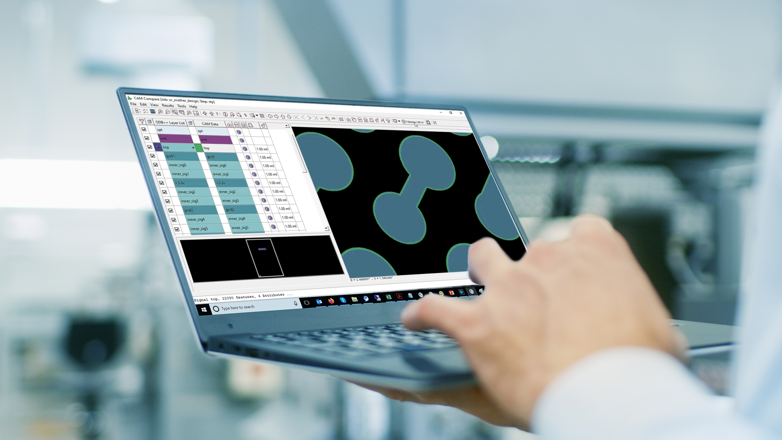
Valor NPI comes coupled with multiple tool kits specifically designed to manage and assist with a DFM workflow. The CAM Compare tool is one of these invaluable tools to members across the NPI team. CAM Compare provides a user with in-depth analysis of any graphical differences between two CAM files, flagging these changes and allowing the user to address them or dismiss them, allowing for in-depth legacy data validation, revision control and helping to flag CAM edits made by fabricators regardless of the CAM tool used. The CAM Compare tool has seen significant updates with the latest version release of Valor NPI, strengthening its versatility and usability.
Typically, comparisons take place between files revisions within identical data formats, however it is also possible to make these detailed comparisons between differing data formats. CAM Compare is capable of performing these graphical comparisons across formats and supports designs stored in ODB++, IPC2581, Gerber 274X, IPC-D-356A, Excellon drill data or other EDA flow data.
3 use models
CAM Compare has three primary uses:
1. Validation of ODB++ data
When migrating between different versions of CAM software, CAM Compare can be used to examine the graphical appearance of these two file types. By comparing legacy Gerber data to the new format, users can be assured that there are no differences between versions. The software scans the two file sets and shows a line-by-line assessment of the differences present. By skipping through, a user is able to review every change present individually.
2. Design revision comparison
When comparing one design revision to another, a digital review can be made with CAM Compare identifying what has changed between the two versions. CAM compare displays the changes that have been made between one design revision to another. The compare result can be used to check if there are any unexpected changes and determine if the stencils or toolings need to be redesigned.
3. Identify fabrication CAM edits
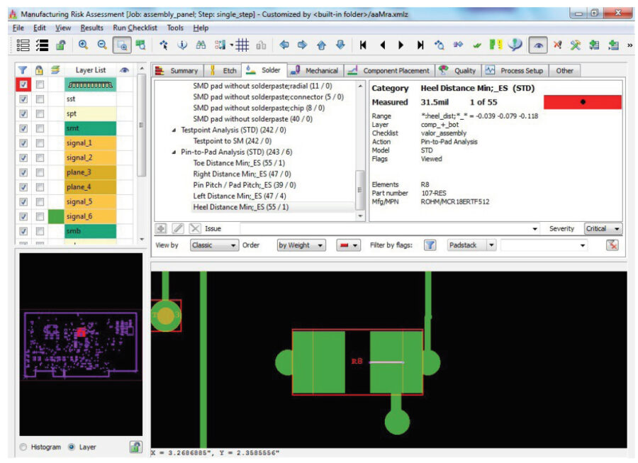
The third scenario in which CAM compare is often used is when comparing the original ODB++ product model with data received back from PCB fabricator that might include edge compensation and drill compensation.
When a user compares design with fabrication data within CAM Compare, they can quickly understand the etch compensation in the CAM data that is made by their fabricator, and determine what significant edits have been made by the fabricator.
PCB CAM files from a CAD tool
In most cases, CAM Compare is able to perform most of the stages required to fully examine and compare two data files. It can read and match reference data, identify matching layers, coordinate registering layers, and compare the result. There are however instances where layout and naming may have changed between revisions. In these cases, it is possible to perform layer matching individually between available revisions.
Explore the use cases for CAM Compare within our short video, or take a test drive today within our Valor NPI free trial.
Explore Valor NPI with our Online Trial
Explore Valor NPI with our free online trial and find out how easy it is to implement the world’s most advanced DFM software. With no download or installation necessary, this simple guided tour provides immediate hands-on experience. Select your desired workflow: