Digitalizing 3D PCB design: converting from 2D models to 3D – part 5 of 8
The role of the circuit board will become even more critical in autonomous and electric vehicles. With so many components and a higher need to verify vehicle safety, having a reliable 3D PCB design will be crucial to ensure the vehicle performs at the highest possible functionality, and will do so safely.
Once the 3D PCB design is complete, it needs to be translated into the real world. The circuit board layout represents the physical incarnation of the circuit. The difficulty is in putting all the necessary electronic components onto a board, and route the necessary copper traces providing the interconnections. This process becomes quite a challenge, as the copper traces cannot physically touch and cross one another. Multilayers are then needed to allow these traces to bridge each other by going into the layers of the circuit board.
This stage in the process represents a critical phase in its development. There are millions of routings possible resulting in a different number of board sizes and layers. However, there are also numerous rules, guidelines and ultimately space limitations that require an optimization approach to achieve all the goals.
Through digitalization, an automation process evaluates thousands of possible routings and quickly plays an integral role in the electronic circuit board layout development process. Downstream development may identify performance problems with the location of a capacitor or controller due to vibration or temperatures. Moving the components would require a new copper trace routing configuration. In the past, this would represent a substantial investment in time. Moreover, it may not be possible to trigger an increase in the number of layers and board size.
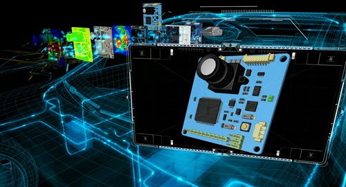
The circuit trace layout process accounts for the topological structure of copper traces and components. To evaluate the physical performance of a model, a 3D CAD representation is required, and this step represents a significant challenge in the industry.
Traditionally, a simplified CAD model is generated to conduct basic simulations of thermal and stress performance; it doesn’t provide the simulation fidelity to support the demands of the next generation electronic systems. This simply will not work in the era of autonomous and electric vehicles.
Developing a highly detailed 3D CAD model of the circuit board layout traditionally would take days or weeks. Solid models of the boards, circuit traces, plated holes, components, solder joints, connectors, heat sinks, clips, cooling fans and housings all demand intricate and time-consuming development.
It’s a painstaking process and generally avoided, which means automation is needed. The capability to take the circuit board layout information and automatically develop the relevant 3D CAD enables the end-to-end product development process.
Having a 3D CAD model enables many other critical processes, including component data management, manufacturing development, design for assembly, design for manufacturing, costing and BOM management.
In the modern day engineering processes where digital twins are utilized to simulate real world physics before hardware is manufactured, and digital threads are critical to virtually manage ever changing product requirements, business/purchasing information. These all play key roles in the digital twin and digital thread processes for product development.
This concludes the fifth part of our series on electronics systems and the challenges to provide solutions for products of the future. In our next blog, learn how thermal solutions play a critical role in the life expectancy of components. If you wish to start from part 1, please click here.
About the author
Greg Roth is the director of automotive and transportation solutions in the Industries Group at Siemens PLM Software. In his current role, he champions CAD, CAE & PLM technologies and processes for companies at a global enterprise level so they can achieve substantial reductions in product development costs and time while improving overall quality. He previously held positions at Ford Motor Company, Eaton Corporation and Amcor Packaging. He was also chief engineer for the CAE and NVH departments at ZF-TRW Automotive North America Braking Systems in Livonia, Michigan. Greg holds an master’s degree in mechanical engineering from the University of Michigan, a master’s degree in electronics and computer controls engineering from Wayne State University and a bachelor’s degree in mechanical engineering from Michigan State University.