Convergent Modeling to avoid reverse engineering bottlenecks
Speeding up an engineering task is always a good thing, but eliminating the task altogether is even better. Take the case of reverse engineering geometry from 3D scanned data, for example.
In a typical process, you capture 3D scan data in the form of a point cloud or a facetted object, and then you go through a tedious reverse engineering process to convert this data to a traditional CAD model with curved surfaces.
There are many products whose development depends on this time-consuming reverse engineering process. A few common examples are:
• Hand-held objects like computer mice, and the handles of guns and power tool, whose “feel” needs to be assessed during development;
• Objects like toys and jewelry, which are often modeled by craftsmen who have no CAD skills;
• Designs that have been modified during physical try-out, such as molds or stamping dies;
• Objects for which no CAD data is available, because it has been lost, or it is owned by someone else;
• Objects that are going to be implanted into the human body, like artificial joints or teeth; or,
• Objects that have to conform to the shape of the human body, such as hearing aids, diving masks or shoe orthotics.
In each of these cases, the design starts out in physical form, and it is then scanned to produce digital data. The 3D scan data typically consists of a “point cloud” or an STL file.
Next comes a “surfacing” step in which the scan data is converted to a traditional CAD model. This is a tedious manual process, and it requires highly-skilled surfacing experts who are often in short supply.
The surfacing step is often a serious bottleneck that delays the start of downstream work, so designers often ask for enhanced functions to speed it up.
We think we have something even better — a new technology called Convergent Modeling that eliminates the surfacing step altogether.
Our vision
CAD geometry traditionally falls into one of two categories. Models either consist of curved surfaces, like NURBS surfaces, cylinders or cones, or they are composed entirely of small planar faces that simulate curved ones. Since they look like gemstones, the latter are often called “facetted” or “polygonal” models.
 Old reverse engineering approaches don’t allow facetted and curvy objects to mix well.In today’s CAD systems, facetted and curvy objects don’t mix well. Because of the way these systems are architected internally, modeling operations that work on curvy objects typically don’t work on facetted ones.
But, imagine a system in which modeling approaches have converged so that you can use facetted objects directly in the same way you use traditionally curvy ones. Or, imagine a further convergence, where you can build objects that are partly curvy and partly facetted, and use them throughout the entire CAD system just as you would expect.
This is our vision with our new Convergent Modeling technology: you can use facetted or “mixed” objects directly in your design work without going through the time and expense of the reverse engineering step described above.
The old and new reverse engineering approaches
The traditional process is illustrated below, using a generic example object that might be a plastic shell for some hand-held gadget.
 The traditional reverse engineering process has five steps.
The steps are:
• Design the external shape using a physical medium such as wood or clay
• Scan the shape and import the scanned data into a CAD system
• Perform “reverse engineering” to construct surfaces that match the 3D scan data
• Offset to get inner walls
• Add details such as ribs and bosses for strength and for attaching other components
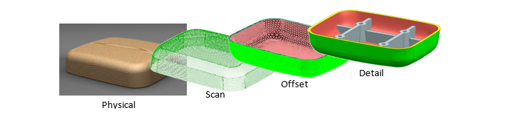
On the other hand, this is what the new workflow looks like using Convergent Modeling technology.
 This new reverse engineering process eliminates a step.
As you can see, the surfacing step has been entirely eliminated. The offsetting and detailing steps have been applied directly to the facetted model that was obtained from the scanning step.
This concludes part one of our series on Convergent Modeling. In part two, George Allen discusses the technology behind this new reverse engineering process and how it fits in with the ability modern CAD systems.
Tell us: How would this new reverse engineering process help your business?
About the author
George Allen has more than 35 years of experience in developing CAD software and in helping major corporations use it to improve their productivity. He is recognized worldwide as a leading expert in the field both by academics and industry executives. George has led the development of several new technologies in the NX CAD software, especially in the area of geometric design. His advice and guidance have served to improve productivity at some of the world’s largest manufacturing companies, including GM, Nissan, Honda, Boeing and Canon. George received his B.S. degree in mathematics from the University of Sheffield and his M.A. degree in mathematics from the University of California.