Fast, Accurate and Easy Fluid Flow Analysis for the Design Engineer

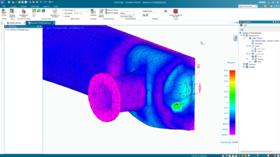
 Visualization of fan assisted cooling of electronic components is one of the many capabilities of FloEFD for Solid Edge.
- The new integration of Mentor Graphics’ FloEFD analysis solution with Solid Edge lets engineers solve airflow and heat transfer issues within and around their designs. And because analysis take place at the same time as design, engineers can examine trends, discount unfavorable options and optimize their designs within engineering timeframes.
This is the second in a series of blog posts about fluid flow analysis – the first focused on the new challenges resulting from modern product designs.
The FloEFD computational fluid dynamics (CFD) tool is easy to learn and can be run without detailed knowledge of meshing techniques that is often demanded by finite element analysis and other CFD software, says Chris Watson, technical manager at Mentor Graphics. The E in FloEFD stands for “engineer” as in “engineering fluid dynamics.” It draws a distinction between the classic CFD user—who’s traditionally been a specialist or highly trained analyst, and the product designers and engineers who can now easily run CFD analyses from inside Solid Edge.
“If an engineer is designing products whose performance is affected by fluid flow or heat transfer, they can do a virtual simulation of that process on their computer directly in Solid Edge,” Watson says. “That’s the benefit. That’s why engineers do it.” They would then make a design adjustment based on information returned from FloEFD and run the analysis again – all the parameters from the previous analysis are automatically stored and reapplied.
“The classic way of doing CFD was with lots of steps that slowed down the whole process,” Watson says. With those kinds of CAD and CFD packages, the first step was getting the geometry out of the CAD program and into the analysis tool. But that step was often riddled with translation errors as engineers had to import the CAD geometry and then clean it up. “And that’s just getting the model ready to run,” Watson says. The Solid Edge and Mentor Graphics pairing, however, allows engineers to work directly with the native CAD model without the need to move it into the CFD solution. That eliminates translation errors and reduces solver time. Engineers don’t have to leave the CAD program to solve for CFD because FloEFD is embedded into Solid Edge. They never leave the Solid Edge interface.
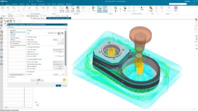
 FloEFD is embedded within Solid Edge for fast setup of an analysis, and easy update of the analysis if the design changes.“Once you’ve done your analysis, you can see how you might change or improve your design, then you can directly alter your CAD model and run that next case and see if you’re improving things or not,” Watson says. “That’s another one of the advantages of working directly within Solid Edge as opposed to going back and forth between an analysis tool and a CAD tool.”
FloEFD can be used to analyze not only the external fluid flow around a part, but also to study the flow through the empty spaces that are inside a part of assembly. This is called an internal flow problem. Engineers can analyze airflow over an airplane wing, but also fluid flowing through a valve. They don’t have to explicitly create a fluid-flow region within the empty valve for solving and any adjustments they make to the CAD model are automatically reflected within the empty flow space.
More Than Electronics
FloEFD is used for a wide array of engineered assemblies and parts that reach well beyond electronics designs, Watson says. “A lot of folks associate our company with electronics and so they assume our tools are for analyzing electronics and electronics cooling,” he says. “And certainly that’s what our company was built on.”
But, to take one example from outside the electronics realm, think of the automotive industry. To figure out how to minimize drag, engineers could study the external airflow around the car as it moves along a highway. To ensure the engine is sufficiently cooled, engineers might model airflow through the engine compartment as well as coolant moving through the engine block and cylinder head. They also use CFD to study airflow through the intake and exhaust system and they even look at how air moves through the inside of the vehicle, where the passengers sit, to determine cabin comfort and troubleshoot HVAC issues.
“It’s amazing how many industries, products and applications relate to fluid flow once you start to think about it,” Watson says. FloEFD can be used to solve many different design challenges across many industry segments – here are a few examples from the automotive industry.