Automation: Part Configurator

This article takes technique learnt in the previous post a step ahead and shows how to configure a Solid Edge model so its variants can be generated programmatically.
The earlier article in the Automation series discussed how to control a parametric part from VB.Net. In this post you learn how to create variations of a part by changing the value of the suppression variables.
Begin with creating a Window Form Application as explained in the previous article. Add a ListBox  and a Button to the Form.
Set properties for the Form, ListBox and the Button as below:
1. Form:
Text: Part Configurator
TopMost: True
StartPosition: CenterScreen
MaximizeBox: False
MinimizeBox: False
2. Button:
Text: Configure Part
Name: btnConfigure
3. ListBox:
Name: lstShaft
With the ListBox still selected, click the ellipsis button  in front of the Items property as shown below:

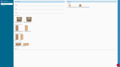
A new dialog pops up titled ‘String Collection Editor’. This holds the items to be displayed in the ListBox for the user to pick.
As shown above type one name on each line. These are the variations of the Shaft that the program will generate.
Click OK when done and Press F5 or from the Debug menu, select Start Debugging ![]() to preview your Part Configurator dialog.
to preview your Part Configurator dialog.
This would be the right time to add Solid Edge references if not so far as explained in this first article in the Automation series.

Press Ctrl+Shift+S to Save All files in the project.
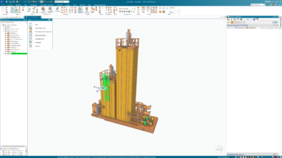
Switch to Solid Edge and create a Shaft with three features – a Taper, a Hole and a Keyway as shown below:
Right click each feature in the PathFinder viz. Keyway, Taper and Hole. Each time select Add Suppression Variable from the context menu that appears.

This adds new variables to the Variable Table one for each of the features. The value of this variable can be set to 0 to un-suppress or 1 to suppress the feature.
In the Part environment, right click anywhere in the graphics area except on the model and select Variables… from the context menu to bring up the Variable Table.
Note the new variables with names FeatureName_Suppress. Try changing the value of the variables from 0 to 1 and observe how the corresponding feature gets suppressed.

With all three features getting suppressed the shaft appears to be a simple variant without any features as shown in image.
Through the VB.Net code, we will change the value of these suppression variables to create a variation of the shaft as per user selection from the ListBox.
Switch to Visual Studio using Ctrl+Tab or Win+Tab.
Double-click anywhere on the Form except on any of the controls. This will open the code window with the cursor placed inside the Sub for Form_Load. Code placed here is executed when the program starts i.e. when the Form loads.
Press Ctrl+Home to go to the top of the code window and add the following lines:
Imports System.Runtime.InteropServices

Imports SolidEdgeFramework

Imports SolidEdgePart

Public Class Form1
The meaning, importance and use of these lines has already been explained in the previous articles.
Also add variables for Solid Edge and variables collection as explained in the previous article:
Public Class Form1Dim oApp As SolidEdgeFramework.Application
Dim oVars As SolidEdgeFramework.Variables
Place the cursor back into the Form_Load Sub and add lines as below:
Private Sub Form1_Load(sender As System.Object, e As System.EventArgs) Handles MyBase.Load

  oApp = Marshal.GetActiveObject(“SolidEdge.Application”)
  oVars = oApp.ActiveDocument.Variables

  lstShaft.SelectedIndex = 0

End Sub
The first two lines for the oApp = Marshal… and oVars = oApp… are already explained in the previous post.
lstShaft is the name of the ListBox on the Form. A ListBox has items in it displayed when the program runs.
Each item has an index number assigned internally. The first item in the ListBox has an index number of 0 while the second item that appears in the ListBox has an index of 1 and so on.

The SelectedIndex property of the ListBox named lstShaft means the index number of the item currently selected.
By setting the value of this property to 0 we specify that the first item in the ListBox be selected. Press F5 again to check this upon which the Form appears as shown in image.
The zeroth item i.e the first item in the list is selected automatically.
If the user selects a variant from the list by clicking it, the SelectedIndex property changes.
The new SelectedIndex value can be checked via the Button on the Form and accordingly the shaft can be configured to render the selected variant in Solid Edge.
Double-click the button Configure Part and type the following:
If lstShaft.SelectedIndex = 1 Then and press <ENTER>. The End If line will be added automatically.
Complete the code as below:
If lstShaft.SelectedIndex = 1 Then
oVars.Edit(“Taper_Suppress”, 0)
End IfIf lstShaft.SelectedIndex = 2 Then
oVars.Edit(“Keyway_Suppress”, 0)
End IfoApp.ActiveDocument.Recompute()
The second item with text Tapered Shaft has the index of 1. If this is selected by user, the SelectedIndex value is 1. If this is so, change the corresponding value of its suppression variable Taper_Suppress to 0 so as to un-suppress it in Solid Edge.
This will create a tapered shaft when the button is clicked.
Similarly, if the SelectedIndex is 2, it means the user has picked the item Shaft with Keyway and to create this variant, the Keyway needs to be un-suppressed by setting its Suppress variable to 0.
This will create a Shaft with a keyway when the button is clicked.
Complete the code as below:
If lstShaft.SelectedIndex = 1 Then
oVars.Edit(“Taper_Suppress”, 0)
End IfIf lstShaft.SelectedIndex = 2 Then
oVars.Edit(“Keyway_Suppress”, 0)
End IfIf lstShaft.SelectedIndex = 3 Then
oVars.Edit(“Hole_Suppress”, 0)
End IfIf lstShaft.SelectedIndex = 4 Then
oVars.Edit(“Taper_Suppress”, 0)
oVars.Edit(“Keyway_Suppress”, 0)
End IfIf lstShaft.SelectedIndex = 5 Then
oVars.Edit(“Taper_Suppress”, 0)
oVars.Edit(“Hole_Suppress”, 0)
End IfIf lstShaft.SelectedIndex = 6 Then
oVars.Edit(“Taper_Suppress”, 0)
oVars.Edit(“Keyway_Suppress”, 0)
oVars.Edit(“Hole_Suppress”, 0)
End If
oApp.ActiveDocument.Recompute()
Note that, to create a variation where two or more features need to be un-suppressed, call the oVars.Edit method twice or those many times – simple as that.
It is customary to copy-paste repeating code.

Tip: In Visual Studio, you need not select an entire line to copy it. Just place the cursor on the line to copy and press Ctrl+C, the line gets copied.
Test your program by pressing F5 and selecting various items from the ListBox followed by pressing the Configure Part button.
Solid Edge should update by unsuppressing feature(s) as per the selection.
By now you must have noticed that after creating a variant – Tapered Shaft with Hole and Keyway – followed by creating any other variant, say – a Shaft with a Hole – it does not update the shaft model.
In the next installment, learn:
1. How to handle this situation.
2. About the Select Case statement which makes the program run faster and more efficiently.
The completed code files are not provided purposely with this post, I would insist you try out the steps and build your own version of the program.
Should you face any problems with coding, the Solid Edge Dev Forum is a click away.
Or simply post a new message.
-Tushar Suradkar
http://surfandcode.blogspot.in

Comments