A New Perspective on Recognizing Holes and Hole Patterns in Solid Edge

Serendipity is the occurrence and development of events by chance in a happy or beneficial way. This happens with CAD features too. Dan Staples famously said that synchronous editing of parts at the assembly level was a feature discovered in a similar sense. Solid Edge is abounding with such features and if you haven’t yet had a chance to use them in the right combination, it was a waste of lucky alignment of particles that are waiting to be explored and taken advantage of.
Vastly unrelated commands like Part Copy and Create 3D have been in existence since the earliest releases of Solid Edge, while ST1 for the first time in the history of any CAD enabled importing dumb geometry and modifying its features like they were created natively. Scale Body, on the other hand, was introduced only recently in ST10. What do these commands have in common?
Well, there is a combo of post-processing commands that render the outcome of these features meaningful. The commands are Recognize Holes introduced in ST5 and Recognize Hole Pattern which was new in ST6. Let’s take a closer look at each of these and how the duo recognition commands compliment them.

Recognize Holes
This command automatically identifies cylindrical cutouts in dumb or featureless geometry and creates synchronous holes out of them. The recognized holes are procedural. This means the holes can be modified using the Hole dialog and its various parameter like diameter, extent and even the type can be changed like natively created holes.

Upon initiating the command, a dialog box pops up almost instantaneously, listing all recognized holes and they are clubbed together according to size and type in rows. Now you can:
- Choose not to identify specific holes of the particular diameter.
- Bring up the Hole Options dialog to change any of its parameters.
- Bypass the automatic recognition for the entire model and specify a face to identify holes from.

Recognize Pattern
Solid Edge can recognize a series of parallel hole features and redefine them as a single pattern. Both rectangular and circular hole patterns are recognized. This command expects the user to fence-select holes to recognize the patterns they form.
All recognized patterns are listed and holes which you selected but did not appear be to be forming a pattern are elegantly highlighted in red. So you can:
- Choose to not recognize a pattern.
- Rename the pattern in the dialog.

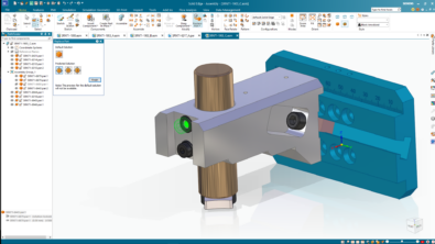
 Note: The Hole Pattern Recognition dialog is modal, meaning you can interact with the model while the dialog is still open. This facilitates interacting with the model and specify the master occurrence as shown in the image above.

Tip: You can also preselect the face for both hole and hole pattern recognition in which case only the holes or hole patterns on that face are recognized.
In the image below, note the two rectangular and one circular profile and the corresponding entries in the PathFinder for the recognized patterns.

Additionally, the checkbox for Recognize Patterns of Hole Patterns does exactly as it says. Here’s an example:

Create 3D
This requires no introduction and there are plenty of videos and articles out there but focusing mainly on the AutoCAD import wizard, selection of regions while few other cover sheetmetal creation from 2D flat patterns and creation of flat patterns from sheetmetal.
These videos stop short of the subsequent post-processing of identifying holes and further recognizing patterns of those holes.
Serendipity: Recognizing holes and patterns if any, after creating 3D models from 2D views takes the Create 3D command to a new level and is a classic example of two features from distant eras in the history of Solid Edge working seamlessly in a beneficial way.
The video at the end of this article demonstrates this.
Import Geometry
With the advent of Synchronous Technology, Solid Edge could import dumb or featureless geometry. It was no longer necessary to have sketch-based features like protrusion and cutouts since these could be modified by placing smart dimensions on the 3D faces directly.
Treatment features like fillets and rounds did not even require dimensions since Solid Edge extracted this directly from selected geometry and modify them using the prodigious Steering Wheel.
This was true for circular cutouts as well. One could simply click a hole and its diameter could be modified directly since Synchronous Technology extracted it on the fly. Recognizing cutouts as holes have additional benefits like changing its type and extent, use saved settings, add a V-bottom angle, threads and start chamfers.
Recognizing patterns of holes can be used for rapid placement of bolts or screws in the assembly since the pattern in the assembly supports existing patterns in the parts.
Part Copy & Scale Body
The Part Copy command inserts geometry from another Solid Edge document into the current part or sheet metal document as a Parasolid body. This command has been around from the pre-ST era of Solid Edge releases. The Scale Body command, on the other hand, was added only in ST 10.
The need to change the size of a 3D model is common in applications such as manufacturing molded plastic parts, where the size of the mold cavity is larger than the resultant part because the plastic shrinks as it cools. Another case is of scale models, which are often produced for prototyping purpose and the most popular method used for this is 3D printing. The 3D printed model needs to fit on the platen of a 3D printer.
This is not an issue in either scenario when using Solid Edge. The Scale Body feature comes to the rescue by allowing to create parts at true size and reduce or increase it by a scale factor later to suit the purpose. This command lets you specify how much a design body reduces or enlarges. For example, to enlarge a part by 50 percent, a scale of 1.5 is used.

Warning: An unavoidable outcome of using the Scale Body command is the hole features are no longer the original size, they are converted to face sets.
The recognize holes and hole patters commands handle this effortlessly as demonstrated in this video:
Download the DWG and STP files used in the video from the links at the end of this article.