The Normal Protrusion and Cutout
A closely competing software to Solid Edge in its latest avatar 2015 introduced Normal Cutout.
This reminds yet another time how Solid Edge has been years ahead of competition in several fields.
The Normal Protrusion and Normal Cutout features have been in Solid Edge for at least last 10 releases – good time to take a review and look at some more examples other than those illustrated in the Help which typically portray the Normal Projection being used for carving or embossing text outlines on to curved surfaces.
A nicely illustrated article on this topic by Solid Edge veteran John Pearson can be read here.
Technically, Normal means ‘at right angles’ as in a view normal to a face or a line normal to a
surface and like Roy Orbison (or Jimmy Grimble), there is only one Normal to a surface at a given point. The difference between Cut and a Normal Cutout lies in to whom the direction of cut is normal to.
In case of the Cut feature, the direction of cut is normal to the sketch or the sketch plane and does not care about the type of surface being cut – plain or curved.

In case of a Normal Cutout, the direction of cut is normal or perpendicular to the surface, actually to the tangent to the surface at all points where it cuts the surface. Same principle applies to the Normal Protrusion feature as illustrated below.
Apart from projecting text outlines for embossing company logos or names, there are several other example applications of the Normal Protrusion and Extrusion commands, most notably in surfacing where the surfaces are not always prismatic or simple revolved.
A typical example is a bottle (what else ![]() ). The job involves creating a recess to act as a gripper.
). The job involves creating a recess to act as a gripper.
The bottle is a simple Revolve feature and the surface created is predictable. Creating a Cut feature would result in a recess whose depth is not uniform since the direction of cut is normal
to the sketch and the imaginary tool meets the surface at different locations while still continuing in the same direction as perpendicular to the sketch or the sketch plane.
When the sketch is first projected onto the surface and then the projected curve used to create a Normal Cutout, the direction of cut is no longer perpendicular to the sketch but is normal to the surface thus creating a recess of uniform thickness.
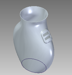
Another prominent example would be of a vase or a simple container which has a freeform surface created using BlueSurf fitted between a circle and an ellipse and guided along two open but connected curves as shown below.
The vase needs to have a raised surface patch and further few cutouts to pass a belt or some
holder arrangement.
For these kind of surfaces and cuts, the Normal Cutout comes in handy. The sketch as shown in the inset is first projected on to the vase surface.
Then a Normal Protrusion is created. Note that the nature or curvature of the raised surface is same as the surface of the vase.

This is followed by rounding off edges and a Thin Wall. After this, sketches for the cutout are created, projected and a Normal Cutout is made using the projected curves.

The use of Normal Protrusion and Normal Cutout commands are thus indispensable in such cases.

Comments