Solid Edge ST9 Part Modeling
This is the part of What’s New that I really get most excited about. There is a lot of new stuff to talk about with ST9. Let’s just jump in.
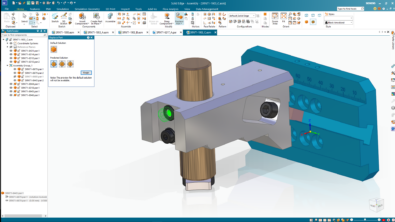
Display Ordered Model In Sync (hybrid display)
This one is for people who work in mixed sync/ordered modes. The gist of the idea is that you can show your ordered features while working in sync mode.
Here is a model I made in mixed mode. The sketches were done in sync, and the lofts were done in ordered. I can be working in Synchronous mode, select a sketch, move it with the Steering Wheel, and watch it update the Ordered features.

Of course you have always been able to do the reverse, working in Ordered, you can move your Synchronous sketches. My example would probably be better to change the length of the first Protrusion, and watch all the lofts update.
There are a couple of settings that allow all of this to happen. Solid Edge Options > General > Recompute Ordered Part After Synchronous Edit is a new setting, and is turned on by default. But you need another setting to make this happen. In Synchronous mode, right click on the Synchronous header in the PathFinder, expand Show All, and select Ordered Body.
Anyway, this is good news for people who have integrated Synchronous tools into your workflows.
Associative Mirror in Sync Part

Another sync/ordered type of enhancement that you will find in ST9 is the ability to “Persist Mirror Associativity”. Synchronous Technology removes a lot of associativity from your modeling. And this is great, most of the time. Sometimes, however, you do need a little associativity. And the Mirror feature is often one of those times. So Solid Edge has added an option to persist the mirror associativity. Remember the terminology for remembering face relations is also “persist”. This means changes of this sort will not rely on the Design Intent settings to drive changes to mirrored (or symmetric) features.

Via the right mouse button menu, you can also break the associativity, so that the Persist condition can be removed from mirrored geometry.
Offset Design Intent
There is now an addition to the Design Intent options called Offset. This will maintain the offset (parallel at a distance) for thin features such as ribs during a synchronous edit. In the past you had to apply a dimension to get this sort of behavior, now it will maintain thickness without a PMI dimension.

Multi-Body Features
Multi-body workflows can be very powerful for various types of design. Master model type work is one such type. This is where you create an assembly as a single part, saving sections of the part out to create individual parts that come back together as an assembly. This is done in many cases to simplify in-context relations. Getting into the how and why about multi-bodies is something for a different article. Here I really just want to talk about what’s new in Solid Edge ST9.
You can select which bodies the cut applies to, which is a great addition to the multi-body tools for this release. This type of functionality affects extruded and revolved cuts, rounds, chamfers, ordered holes, and pattern/mirror of multi-body features.

Solid Sweep

Solid Sweep is a feature that enables you to simulate cuts with an end mill, or the space that a moving part will occupy. Sometimes sweeping a 2D cross section along a path does not give you the type of geometry that you are looking for. For example if you are trying to cut a lead screw into a rod.

Just in case you were wondering, this is one of the applications of multi-body modeling. You model the rod, and then as a separate body you model the end mill or cutter in its starting position. Then apply some sort of a path. In this case, a helix was used. The path must intersect the cutting tool.
This method is great for visually showing this sort of cut, or when you have to actually create the geometry in CAD because you have to do some sort of simulation or 3D print. To actually manufacture this part in steel, your shop would work from standard data rather than running toolpaths on this geometry.
Spiral Curve

The Spiral Curve option is just another option on the Helix dialog. You still have to initiate it with an axis, but you can specify the spiral by a combination of any 2:
- End diameter
- Turns
- Radial pitch
Point Support in 3D Sketch

3D sketch is one of those tools that I think gets underused in Solid Edge. 3D sketches can be used as all-around problem solvers when you have geometry you need to figure it out, and you can do it by hand calculations, sometimes it’s just easier to let the geometry figure itself out.
Points in 3D sketch do a great job of providing a reference that is not the origin or another coordinate system. They also keep track of virtual intersections between lines when rounds are involved.
I’ve used 3D sketch points in the past to mark where a light beam touches a surface, or use 3 of them to define a plane.
This feature is also evidence that Solid Edge is willing to revisit even a new feature and add to it when it makes sense. The 3D sketch itself is rather new in Solid Edge. As soon as it became available, one of the things people were asking for immediately was the 3D sketch point. And now we have it.
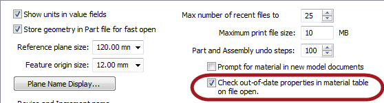
Material Table
The Material Table can now be displayed in three different ways: Library, Group, or Material display, sorted in ascending or descending order.


Also, when properties in the library do not match the part (called out-of-date), the properties will be flagged.
Assigning a material to a part will optionally color the part to the face style defined in the Material Table.
(It sounds like Solid Edge is becoming more conscious of the display and appearance of models…)
Material properties are created as variables and can be exposed as file properties. Start imagining now how you are going to make use of this.
Summary
I’ve got to leave a little excitement for later. These are some pretty good enhancements, and it’s hard to believe how much they squeezed into this release. With all of the Data Management stuff, it’s amazing that they were able to do anything else at all.

Comments