Sheet metal intro
This article will start a series on Solid Edge sheet metal. My goal is to go through the functions to give new users a taste for how it works, but also try to find tools that really go beyond where we expect mid-range tools to go.
Yes, I remember I was doing Inspect tools, but the last article on that one showed me that I need to do more research on that before returning to it.
Sheet metal is one of those areas where Solid Edge has always had a leg up on the competition. Let’s go through a few basic features and get a feel for how this works.
As a bit of a disclaimer, I’m not a sheet metal manufacturing expert, but I understand the concepts involved. I’m primarily a plastics guy, but I’ve done enough sheet metal to hold my own to some extent. I recognize that understanding the physical process and machinery involved in manufacturing sheet metal parts is key to good design practice. This blog article is not going to attempt to make you a wizard at either manufacturing or design, but rather to help you understand the tools so you can create whatever you need to create, and work through your design and manufacturing processes with confidence in the CAD tool side of the equation.
Also, I’m aware that some shops don’t like design guys telling them how to manufacture parts, and some shops may require the design to specify exactly how things are to be done. I’m not here to tell you how to deal with that kind of situation, I just want to help you understand the CAD so you can deal with whatever comes up. If I present a workflow that doesn’t match your workflow, then just take what you need and leave the rest.
Moving on, sheet metal parts in Solid Edge are a different type of part. You have to start them from a sheet metal specific template. You can work with Ordered or Synchronous sheet metal, and we will take a look at elements of both, although I lean toward Synchronous modeling because it shows Solid Edge’s unique strengths over the rest of the industry.
And just to be clear here, in Solid Edge we are talking primarily about straight brake press type sheet metal bends. We aren’t talking about stampings or deep drawn shapes, although we will get into some of that. We’re talking primarily about straight brake press type bends.
 Here are the sheet metal tools that are available when you open a new part using a sheet metal template. There are two ways you can start: one is with a closed profile and the Tab tool, the other is with an open profile and the Contour Flange. Based on the tool icons, that should be self-explanatory. The Tab tool creates a flat sheet with a sketched outline, while the Contour Flange produces an extruded open thin-walled shape.
 Solid Edge Material Table, Gage Tab
Regardless of which tool you select, you will have the option to set your material defaults using the Solid Edge Material Table. If you have your material thicknesses and properties set up in an external Excel spreadsheet, you can specify that on the top of the Gage page. Or you can specify the material thickness using the gage dropdown list. Finally, you have the option to manually specify the thickeness, default inside bend radius, and relief depth and width for those times when bend reliefs are needed.
Also, you will need to establish the bend equation properties up front. If your shop requires you to provide them with an accurate flat pattern, this will be vitally important. Some  shops may want to figure their own flat patterns for various reasons. However it works at your company, you should work with your shop to understand how they calculate how much the bends stretch the material during the bending process for various materials, thicknesses, and bend angles.
When sheet metal bends, it compresses slightly on the inside of the bend, and stretches slightly on the outside of the bend. This means that somewhere in the thickness of the metal, there is a neutral plane where the material does not stretch or compress. Generally this plane is 33% of the thickness measured from the inside of the bend, but there are a lot of factors that can affect this. This is where the “neutral factor” comes in. The smaller the neutral factor, the more of the material will stretch, meaning that your original blanks must be slightly smaller to get the correct final size. Some shops will use a custom formula in some situations, so keep an eye on this, especially if you work with multiple shops with different types of equipment.
Material Tab
The Material tab of the Material table enables you to select a material from a list, or to add to the library to add your own materials. The materials provided aren’t all-inclusive, so you may have to include your own properties if you are working with something special.
This list is really meant for part weight and analysis or simulation work. The gage tables on the other tab generally include material, as well as thickness, and other factors like heat treating.
I’ve started this part by sketching a rectangle centered on the origin, and using the Tab tool for the first sheet metal feature.

You get the arrow shown in the center of the feature to determine the thickness. You can also key in a thickness value while the small box on the corner is there. If you are using Ordered modeling, you can always come back and change these settings. If you are using Synchronous modeling, you can also make the changes, but you will use the steering wheel to reposition the part or change the thickness instead of editing a feature in the Pathfinder.
 Flanges
Synchronous sheet metal doesn’t have any special command for creating regular flanges. You just click on an edge where you want to add the flange, and pull on the arrow in the direction you want to add the flange.


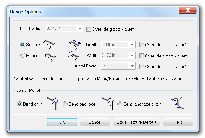
When you start this, you can key in the length of the flange, as well as the angle of the flange. You also get a Flange CommandBar where you can set flange options.
You already set some of these flange options in the Material Table as defaults for the entire part, but you can also control individual bend radius values and bend relief settings.

Bend Reliefs
 Just for reference, it looks like the Square and Round options are not labeled. These are bend relief settings. Bend reliefs are at the ends of bends that do not go all the way across the part. That’s a bad word description, so here’s a screen capture. By the way, these reliefs use the Round setting.
Bend reliefs are necessary because if they were not there, there would be a complex transition between the bend and the flat. Parts can be manufactured without the bend relief, because the real world bending process doesn’t have any problem creating the complex shapes, but the CAD tool is different. If Solid Edge had to create the real world transition in the area of these reliefs, it would make the model unnecessarily complex.
Summary
I’ve written way more than I intended to, and still didn’t get very far. Must have gotten a little carried away with some of the background information. Come back on Friday, and we’ll work through some more sheet metal features.


Comments