Sheet Metal Reliefs and Corners
 Last time we had just made a flange on a simple part. This time, let’s take a look at some of the flange options.
Partial Flange
One of the options is Partial Flange.The Partial Flange takes an edge flange dragged off of an edge, like the one on the left, and turns it into a flange that only goes part way across like the one on the right.
I know former Works users are chuckling, and current Works users have their eyebrows raised. To do this in Works is an incomprehensible process with editing a sketch that never existed.


Since this is Synchronous, to dimension this, you just apply dimensions directly to the edges of the model. Most of the functions with dimensions in Synchronous mode are pretty intuitive, and applying dimensions directly to the solid couldn’t get any more intuitive.
Bend Relief
 Synchronous sheet metal is pretty cool, even cooler than just normal synchronous modeling, if you’ll excuse that word. For example, if you make a partial flange as above using all the defaults, the software makes relief cuts at the end of the bends, as shown to the right. If you move the flange to the inside of the part, the relief cuts actually move with it. What Live Rule is that?!? Some kind of magic, but it’s a good thing. You do have to disable the Maintain Coplanar Faces Live Rule to break the default relationship between the face of the flange and the thickness face of the edge of the sheet metal part.
 When you move the flange outside of the part, the relief cuts go away, as you’d expect, but then if you move the flange back inside the part, the relief cuts show up again just the way the default settings created the original reliefs.


To me this was very surprising. I expected to have to reapply the relief cuts using some special tool. Synchronous sheet metal is not new, but this to me shows that those guys were paying attention when they did add this function.
The other options on the Flange CommandBar include the Material Side, which determines whether the inside or outside of the part is flush with the edge, and the Measure Point, which determines whether the flange height is measured from the inside face or the outside face.

We’ve already talked about the unmarked bend relief settings at the top of the Flange Options dialog, but there is also a set of settings at the bottom for corner relief. The illustrations aren’t very good, because they don’t really show what causes the corner relief to exist. To get a corner relief, you’ve got to have a corner. A corner is created by the intersection of 3 orthogonal faces.
Corners
The “Bend only “ option is shown below at the right, followed by its flat pattern. This is where a little triangle is cut out of the corner. Again, this is just to avoid showing what happens in real life, which is some twisted, complex geometry right at that corner that would be bent by both bends. The metal doesn’t have any problem twisting like that where bends overlap, but showing the twist in CAD is computationally too expensive, so they take a little shortcut. We tend to show it with the corner knocked out even though you don’t really need to do that.


The “Bend and face” option is shown on the left,immediately followed by its flat pattern. The whole flange is trimmed back so the bends do not overlap at the corner.
The final option, “Bend and face chain” is not shown, but would occur if the “Bend and face” option had another flange coming off of the short blue one, such that the second flange would also be trimmed back.
 Corners give you another option with the Close 2-Bend Corner tool. This allows you to take either of the corner types mentioned above and close the gap between the flanges.
If you use the Close 2-Bend Corner tool, you can take the two corner types shown above and they will look like the closed corner shown below, with the flat pattern to the right.

 The way this one works is that you select the tool first, found on the Home tab, Sheet Metal group. Then select the two bends that would be overlapping, and set the gap distance between the inside edges of the flanges.
Again, notice that the corner is left with an open hole. If you create the blank the way Solid Edge shows it (with the square notch), then you’ll get the hole at the corner, but if you produce the blank without the notch, you’ll just get a small area where the bends overlap and produce geometry that’s hard to show in CAD. There’s probably a better way to describe that.
The other tool shown with the 2-Bend Corner is the Rip Corner, which is used in situation where you start with a 3D model and want to make it into a sheet metal part. Say you have a box, remove the top and think wall it. To flatten the box, you have to rip the corners. I won’t demo that here unless someone really wants to see it.

Flatten
And then you have to remember that to get the flat pattern, go to the Tools tab, and the Model group (left end), select a face to keep flat and an edge to go along the X direction, and right click.
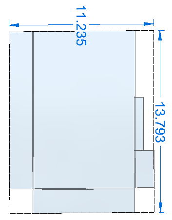
Notice that the flat pattern itself gives you a dotted sheet size, with blank dimensions.
We’re not making very fast progress through this stuff, but we are hitting all the details I can find.
The sample part I’ve been working on is attached if you want to look at the reliefs and corners.

Comments