ST8: Helical Curve
One of the things I like best about Solid Edge development is that when a new release hits, they have their ear to the ground to pick up the reaction from users. I think that’s one of the things that led to this next feature. ST7 had the 3D sketch functionality added to it. Very useful functionality, but when you start playing with it, there are some things it leaves you wishing for – like the ability to create springs, and the Helix as a curve feature was born.
But there’s a great distance between an idea for a feature and a new functional feature in the software, and again Jeff and Aditya and the gang delivered what I think is a really first rate feature.

First of all, where do you find it? You can find the Helical Curve command button on the Surfacing tab, in the Curves group.
When you start the command, the PromptBar tells you “Click on a keypoint, spacepoint, line, circle, cylinder face or cone face to define the axis.” If you don’t have any existing geometry that you want to build from, you can just click anywhere on the blank screen. This is probably  what is meant by “Spacepoint” – just a point in space, not an actual entity. The first two points you click in space define the axis of the helix, and then Solid Edge asks for a third point along a red dotted line in a direction perpendicular to the axis, which defines the start point and thus overall diameter of the helix. This is a very fast and clever way to define the helix. It works with or without other geometry to use as reference.

The Helical Curves Parameters dialog allows you to specify several properties of the helix:
- Constant, variable or compound pitch
- Length and Turns, Length and Pitch, or Pitch and Turns
- Left or Right handed (clockwise or counterclockwise)
- Taper: None, by Angle, by Diameter
- Start diameter
You can also save settings (like a set of “favorites”) to reuse them later on, especially important for complex specifications.
The Compound option enables a table you can use to specify the diameter and two of the other parameters Length, Pitch, or Turns. This gives you a great many options for creating the helical portion of many custom springs. (Non-helical portions of springs can be created using Keypoint curve or spline curve).
If you create the Helical Curve in Synchronous, you can use the Steering Wheel to move and rotate it, but you will not be able to re-specify the helix. For that reason, I recommend that you use this primarily as an ordered feature, so that you can edit the curve after creation.

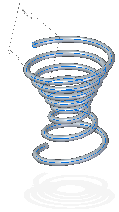
To make the curve into a spring, create a plane Normal to Cuve at the end, draw your cross  section, and sweep. Remember that the cross section diameter cannot be the same or larger than the minimum pitch value, otherwise the sweep will intersect itself.
One question I’ve heard frequently is if this tool allows the creation of a flat spiral. The direct answer is no, but you can project the helical curve onto a sketch plane, which should give you a good bit of control over the flat spiral. The orange highlighted entity shown below is a spiral sketch created in this manner.


Comments