When we left our engineer friend last week, he was starting to work on the engine of his pressure washer, but it was such a mess in his old CAD software that he just decided to open it up in Solid Edge, because to be honest, things couldn’t get much worse for him. It turned out that Solid Edge has a lot of effective translation options, and also has tools that make what other CAD vendors consider “dumb geometry” work like native geometry.
When he opened his engine subassembly in Solid Edge, he was surprised to see that there were actually some mates from his original SolidWorks assembly in there. Let’s drop in again and see what’s going on in the office today.
To work inside the motor, he’s got to make a section view. Section views in Solid Edge enable you to cut some parts and leave others uncut. You can also turn them off and back on very easily, by just using the check box in the Pathfinder. Most items in Solid Edge have a checkbox in the Pathfinder, allowing you one-click access to turn them on or off. It saves a lot of time over needing to right click and find Hide/Show in the menu.
You could avoid a section view by just turning off the Block Casting and the Gear Box Cover, maybe also the Engine Cover parts.
Looking through the online Help for the migration tools, the engineer learns that not all mates come across. The mates that get migrated are face-based mates and Fixed (grounded) mates. Mates involving edges, vertices, sketches, axes, or planes are not brought over as of ST6. Still, face-based mates are the bulk of your mates. You can see in the screen shot below, that when the Block Casting part is highlighted, the first mate that appears in the list is a Ground mate, so the assembly has a main part to act as ground. You can also see that the engineer mated many of the other parts in the assembly to the ground part, so his good practice in old software follows him to his new software
.
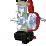
The first part the engineer is worried about in this assembly is the crankshaft. He notices that there is significant interference between it and some of the other parts in the assembly, but mainly just wants to make sure that it is located accurately with respect to the Block Casting. So he tries to move it to see how functional the mates are coming across. He clicks Home > Modify > Drag Component, and drags a point on the crankshaft. It works. “You’ve got to be joking!” Incredulous that enough mates came through a translation to allow the main mechanism which includes 5 parts besides the base casting to function in Solid Edge.
If you want to get a little practice mating parts, this is a good assembly for that. And for the rest of this, the engineer was nice enough to provide us with a YouTube video of how he would have put the parts together if that had been needed. He felt guilty for skipping so much work ;0)
Stay up to date with the Siemens Software news you need the most.
Get Started


Comments