Huntsville Solid Edge User Group Meeting
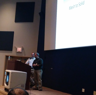
Solid Edge users in Huntsville Alabama are lucky people. Having the mother ship so nearby has some definite benefits. This past week I was in Huntsville for meetings, and just out of luck happened to be there on a night when they were holding a user group meeting. Even luckier than that, they presented 3 topics that I was very interested in: 3D print, Keyshot rendering, and Mesh to Solid.
Peter Llewellyn of the Learning Media Development group organized the meeting. Food, drinks, a nice auditorium, and some interesting Solid Edge related presentations.
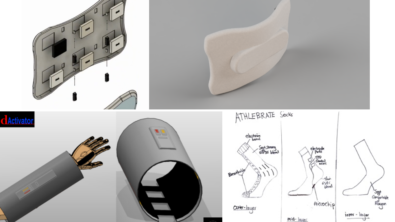
 Paul Carter did a nice presentation on a bunch of renderings he did around a diamond that he modeled. Paul’s my kind of obsessive freak. Anything worth doing is worth overdoing. I think I got this quote right from him: “I’m probably going to wind up losing my job because I am Keyshotting all the time.” I’ve been right there. He just got fascinated with refractions in transparent materials, got lost in the obsession of modeling a perfect diamond, and then cranked up the number of reflections in Keyshot and left a rendering running for …and I think I heard this correctly… 6 days.
Anyway, Keyshot is cool, and something all Edgers need to be up on.
 There was also a very interesting presentation from a customer on moving data from mesh to solid. This is one of my favorite topics to rant about. Mesh data is called a lot of things and comes from a number of sources. You can call it point cloud, subdivision, tessellated, stl, etc… and it comes from 3D scanners, 3D print export, CGI software (like 3DSmax), radar, mri, graphics display data, and others I’m sure. It’s just a collection of 3D points representing the outside of an object. The space between points is usually represented as planar triangles. CAD data is more accurate because it uses variable radius curves and continuous surfaces.
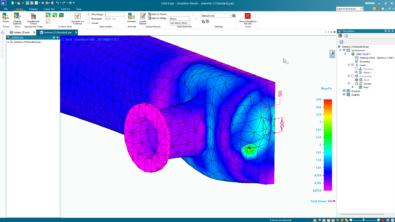
The trick for a long time has been how to go from this collection of points to a solid. The customer who gave the presentation was taking what I thought was sonar scan data of a submarine hull, and represented as a very sparse set of points (lots of space between points), and ran it through a set of free CAD or mesh translators to come up with something that was useful for simple visualization in Edge.
The presenter said his method was to use NETFABB to refine the mesh, and export to STL. Then use FreeCAD to convert STL to STEP and open STEP in Edge. This gives you a model that looks like it was whittled with a chain saw. But it does give you a model.
In my consulting days I did a lot of this type of conversion, but it was all done on (badly) 3D scanned data. Then I had to lay splines over the points to make real NURBS surfaces. This was painful. You can simplify the process with some software (Geomagic, Tsplines), but this is not available as part of Solid Edge at this time. This type of data is becoming more and more important in real engineering settings, so I believe CAD tools are going to have to start dealing with this without some $20k auxiliary tool.

Comments